We begin with a nod to the old adage that a small misstep can ruin a big tool, and that warning still holds true for charging systems. We’ll map how reverse polarity harms packs, outline common mistakes, and pin down a disciplined verification process before any plug-in. Our method is precise and repeatable—design safeguards, test protocols, and handling rules that minimize fault energy. If you want to prevent costly damage, follow these steps closely as we unpack each safeguard and check.
Key Takeaways
- Use diode-based protection and MOSFET reverse-blocking to prevent harmful reverse current during charging.
- Enforce correct connector orientation with consistent geometries and tactile cues to avoid misplugging.
- Implement pre-connection polarity checks and interlocks, verifying labeling, color codes, and pinouts before charging.
- Incorporate fast-acting fuses and safe connectors; maintain clear labeling and robust insulation to minimize polarity errors.
- Conduct ongoing polarity integrity tests, monitor voltage/current/temperature, and isolate any anomaly immediately.
Understand How Reverse Polarity Harms Charging
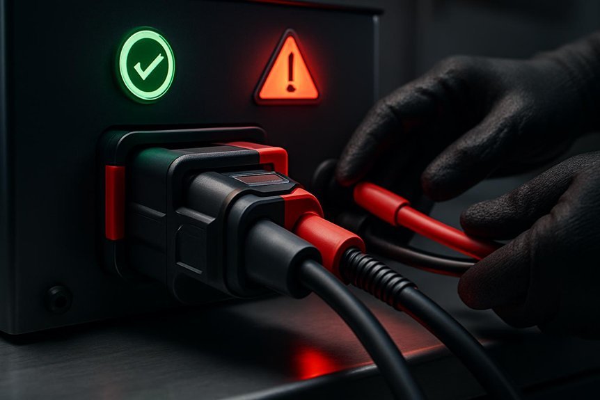
Reverse polarity, if undetected or applied during charging, can cause immediate electrical stress and delayed degradation. We understand how this harms charging by introducing improper current paths that elevate cell impedance and heat generation. When polarity is reversed, protective devices may not engage as intended, allowing transient surges to propagate through modules and connectors. This accelerates electrolyte breakdown and accelerates age-related capacity loss. We quantify risk by monitoring voltage differentials, current waveforms, and temperature rise, then compare against baseline safety thresholds. Our approach emphasizes safety protocols, including clear labeling, redundant polarity checks, and interlocks before connection. We document each step to ensure repeatability and traceability, so readers can anticipate fault modes and maintain system integrity with disciplined, verifiable procedures.
Identify Common Polarity Mistakes in Daily Setups
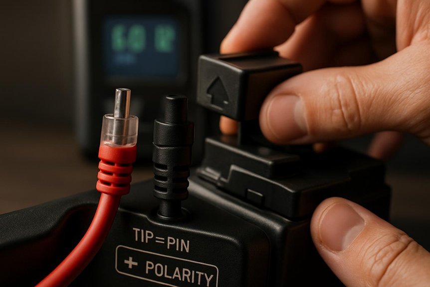
Mistakes in polarity are common in daily setups and can quietly undermine charging safety. We observe how improper connector orientation, mixed polarity indicators, and reused cables contribute to polarity errors. We systematically check labeling at both charger and device interfaces, confirm cable integrity, and verify that polarity symbols align with the actual conductors before pluggin g in. We document color codes and terminal markings, ensuring taping or masking doesn’t obscure critical signs. We avoid improvisation: never rely on memory or assumptions about port compatibility. We emphasize secure cable routing to prevent pinched conductors that alter polarity paths under load. We train users to pause and confirm every connection, recognizing that even small deviations jeopardize charging safety and may enable reverse current or arc events.
Test for Polarity Safety Before You Plug In?
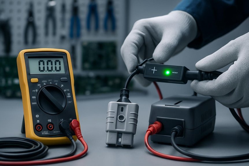
We perform Polarity Safety Checks before any connection, confirming charger and battery polarity match the marked terminals. Our Pre-Charging Verification Steps include inspecting leads, testing continuity, and validating connector orientation to prevent misplugging. We’ll communicate results clearly and proceed only when all checks pass, ensuring safe, reversible charging conditions.
Polarity Safety Checks
Before connecting a charger, we perform polarity safety checks to confirm that the positive and negative terminals align with the device’s labeling and the power source. Our procedure verifies connector polarity against the device’s documented conventions, then cross-checks color coding, pinout, and housing markings to prevent misconnection. We assess the header and plug geometry for unmistakable engagement, reducing ambiguity during insertion. Polarity awareness guides every step, ensuring that the plug’s positive pin mates with the device’s positive contact and likewise for the negative path. We also evaluate the compatibility of the power supply’s connector with the device port, noting any ergonomically subtle cues that might mislead users. connector ergonomics are considered in our checks to minimize handling errors and promote reliable, safe charging.
Pre-Charging Verification Steps
How do we guarantee polarity safety before plugging in? We begin with a structured pre-check that confirms connector alignment, cable integrity, and contact cleanliness. We verify polarity indicators and measure continuity to prevent misconnection. Next, we inspect insulation resistance, ensuring no hidden shorts or leakage paths exist between live, neutral, and ground. We validate that protective earth bonding is intact and that any residual voltages are discharged before contact. We document each step to establish a verifiable trail, reducing ambiguity. By addressing polarity myths and safety myths through repeatable tests, we foster a shared baseline of care. Finally, we confirm the power source state and shielded routing, then proceed only after all readings meet defined tolerances.
Design Practices to Prevent Polarity Reversal
We examine design practices that guard against polarity reversal by enforcing proper connector orientation and integrating diode-oriented protection. We’ll outline how consistent connector geometry prevents misalignment and how diode-based safeguards stop reverse current from reaching sensitive circuits. This discussion starts with the essential criteria for orientation and the rationale for diode placement, then moves to concrete implementation steps.
Proper Connector Orientation
Ensuring correct connector orientation is essential to prevent polarity reversal during charging. We, as engineers, implement strict guidance on connector orientation to ensure consistent, safe polarity across all interfaces. By aligning housings, markings, and keying, we minimize misconnection risk and verify polarity before booting. Our procedure emphasizes tactile and visual cues, plus fail-safe interlocks that prevent arcing if misalignment occurs. Practicing disciplined assembly and routine checks confirms safe polarity at every stage of charging. The following table summarizes orientation concepts for clarity.
| Column A | Column B | Column C |
|---|---|---|
| keying ensures | markings align | interlocks prevent |
| Safe polarity | Connector orientation | Verification step |
Diode Oriented Protection
Diode-oriented protection provides a robust, low-loss method to safeguard against polarity reversal during charging. We implement a dedicated diode path to block reverse current and ensure current flows only through the intended route. First, we select a diode with appropriate current rating, forward drop, and reverse voltage headroom, aligning with system supply characteristics. Next, we determine the diode orientation to guarantee that any inadvertent plug rotation or connector misalignment cannot forward-bias the protection network incorrectly. We place the diode in series with the charge input, or use a dual-diode, orientation-sense arrangement for redundancy. We verify that reverse polarity events trigger only negligible leakage and do not affect essential circuits. Finally, we document test procedures and observe consistent behavior across temperature ranges and repeated cycles.
Protective Components: Fuses, MOSFETs, and Ideal Diodes
What protective components best thwart reverse polarity and overcurrent events, and how do we select them for reliability? We do this with a disciplined combination of protective fuses, mosfet safeguards, and ideal diodes, chosen for response time, voltage rating, and thermal behavior. We prioritize fast-acting devices for short spikes and higher-rated parts for sustained faults, ensuring margin above expected loads. Selection criteria include package, ambient temperature, and fault current profile, plus reliability data and test results. We design guard rails that isolate fault paths and minimize energy deposition in the source. Our approach balances protection with efficiency, preventing nuisance trips while preserving charge acceptance.
- protective fuses and fast trip characteristics
- mosfet safeguards and reverse-blocking capability
- ideal diode behavior and low forward drop
- reliability testing and environmental considerations
Safe Connectors and Cables for Charging
How do we guarantee safe, reliable power transfer when connecting chargers to cells and packs? We assess connector geometry, polarity indicators, and mating integrity to minimize misconnection risk. We select safe connectors that enforce correct orientation and provide tactile cues for proper engagement. Cables must withstand charging currents, thermal cycling, and repeated mating without impedance growth. We specify conductor gauge, shielding, and strain relief to prevent accidental disconnections or shorts. We require defined contact resistance and robust sealing against dust and moisture in relevant environments. Labeling and certification align with safety standards, ensuring traceable compatibility across devices. We emphasize durable cables and safe connectors that preserve polarity, reduce arcing, and simplify fault diagnosis during maintenance and testing.
Handling and Storage Duties That Prevent Reversals
Are we sure we’re handling and storing cells correctly to prevent reversals during charging? We ensure reversal prevention through disciplined handling storage practices that preserve polarity integrity and minimize cross-contamination. Our approach is procedural, repeatable, and data-driven, with clear responsibilities and checklists.
We prevent reversals with disciplined, data-driven handling, labeling, and strict polarity integrity checks.
- Proper labeling and segregation of cells to avoid mix-ups
- Controlled environments for storage, temperature, and humidity
- Routine polarity checks before connection and after storage
- Immediate isolation if any anomaly is detected to prevent damage
Troubleshooting Polarity-Related Charging Failures
We systematically verify polarity integrity by first detecting potential polarity errors and confirming supply and battery connections are correct. If anomalies arise, we perform safe reversal troubleshooting to determine whether a reversed input, faulty wiring, or controller misconfiguration is causing the fault. We’ll document findings and apply corrective steps with a focus on preventing damage and ensuring safe, repeatable charging performance.
Detecting Polarity Errors
When diagnosing polarity-related charging failures, we first verify connector orientation and cable integrity to rule out simple mis-plug or damaged leads.
- We perform polarity monitoring across the input path to detect swapped or inverted connections promptly.
- We cross-check connector pinouts against the device’s expected mapping, logging any deviations for traceability.
- We execute charge protocol validation to confirm that negotiation and timing follow the intended standard without handshakes failures.
- We validate insulation resistance and continuity under load to distinguish transient faults from persistent polarity errors.
This structured approach minimizes false positives while preserving safety. If anomalies persist, we document conditions, reproduce the fault, and isolate the fault location, ensuring corrective actions address root causes rather than symptoms.
Safe Reversal Troubleshooting
Safe Reversal Troubleshooting builds on the polarity checks we discussed earlier. We approach failures with a methodical, reader-facing stance, focusing on reliable diagnostics and repeatable steps. We start by confirming connector integrity, then verify cable orientation, and finally test with controlled loads to observe behavior. If readings indicate inconsistency, we document the exact polarity state and trace the path to the fault. Our goal is safe miswire avoidance and reinforced polarity awareness, ensuring we detect misconnection before damage occurs. The table below visualizes typical fault scenarios and responses.
| Scenario | Observation | Action |
|---|---|---|
| Miswired input | Irregular voltage polarity | Stop, rewire correctly |
| Intermittent contact | Fluctuating readings | reseat connections |
| Ground loop | Noise on line | isolate and measure |
| Shield breach | Anomalous current | inspect shielding |
| Unknown fault | No clear pattern | escalate with diagnostics |
Real-World Scenarios and Quick Remedies
How do real-world charging scenarios challenge protection against reverse polarity, and what quick remedies keep systems safe? We outline practical cases and remedies, focusing on reliability under imperfect conditions. Misleading indicators can mask polarity faults, so we verify signals with independent continuity checks and redundant sensing. Accidental disconnections introduce transient reversals; we mitigate with robust fuses, delay-before-connect logic, and tactile interlocks that prevent rapid reenergization. We also emphasize correct cable mating, shielded paths, and consistent grounding to reduce false positives. Quick remedies center on immediate isolation, rechecking polarity, and reinitializing charging cycles only after verification. Our approach blends diagnosis, preventive architecture, and safe reset procedures to maintain protection integrity.
- Misleading indicators prompt independent sensing
- Accidental disconnections managed with safeguards
- Redundant polarity checks before engagement
- Controlled reinitialization after verification
Quick-Start Checklist for Safe Charging Transactions
First, we outline a concise, step-by-step Quick-Start Checklist to guarantee safe charging transactions. We begin by confirming device polarity and connector compatibility to prevent misconnection, then verify supply voltage and ground reference before any engagement. Next, inspect cables for wear or insulation damage, and ensure connectors are clean and fully seated. Establish a safety mindset by deploying appropriate protective gear and confirming emergency shutoff access. Activate monitoring for temperature, current, and voltage during initial engagement, and set thresholds that auto-disconnect on anomaly. Document each step for traceability, and maintain a predictable sequence to avoid reverse polarity incidents. Train operators on recognizing fault indicators and maintaining a calm, methodical approach. Always reassess conditions periodically, reinforcing understanding polarity and safe charging practices.
Frequently Asked Questions
Can Reverse Polarity Occur With Simultaneous Charging From Multiple Sources?
Yes, reverse polarity can occur if charging sources aren’t synchronized. We assess environmental conditions, verify polarity safety, use proper diodes or active switching, and ensure grounds and connectors align to prevent reverse polarity during simultaneous charging.
How Do Environmental Conditions Affect Polarity Safety During Charging?
Environmental effects can alter polarity safety during charging, we assess humidity, temperature, and contamination to ensure proper insulation and secure connections, then adjust charging parameters. We notify readers of risk, implement safeguards, and document testing for charging safety.
Are There Indicators That Warn of Impending Polarity Reversal Events?
We do detect indicators, signaling impending polarity reversal events via voltage drift, noise spikes, and thermal anomalies. We monitor inductor sizing and connector material health, implementing thresholds and alarms to prompt safe shutdown before failures occur.
Do Cheap Connectors Increase Risk of Hidden Polarity Issues?
We believe cheap connectors can raise hidden polarity risks and undermine connector reliability across charging interfaces, so yes, low cost parts may increase issues we’ll need to mitigate with verification, robust designs, and thorough polarity testing.
Can Battery Chemistry Influence Polarity Protection Effectiveness Over Time?
Yes, battery chemistry influences polarity protection over time. We examine chemistry effects on internal impedance, electrode stability, and protective circuit tolerance, and we adjust polarity protection strategies accordingly for reliability and consistent safety performance.
Conclusion
We’ve built a steadfast bridge between parts and people, guiding every plug like guardians of a harbor. When polarity threatens, we’re the lighthouse: clear labels, checks, and interlocks flashing in precise sequence, fuel lines of power cut only if danger looms. With fuses, MOSFETs, and ideal diodes standing guard, we steer currents away from harm, test before connection, and keep cables orderly. Together, we ensure charges arrive safe, unwavering, and ready for the next voyage.