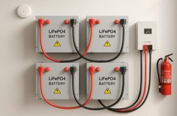
Recent data show that poor protective grounding contributes to over 30% of electrical faults in high-capacity charging systems. We must establish low-impedance earth paths, verify continuous bonding, and coordinate fast fault isolation to minimize shock risk and energy dissipation times. This discussion will guide you through robust design, testing, and maintenance strategies that keep hubs and fleets safe and operational, and it will reveal the practical steps you can apply right away to prevent cascading failures.
Key Takeaways
- Establish low-impedance protective grounding paths linking enclosures, frames, and earth to ensure rapid fault current dissipation and minimal shock risk.
- Use coordinated bonding to create reliable metallic convergence without altering impedance, aiding fault localization and maintenance.
- Implement protective relay schemes and fault isolation (sectionalization, fast disconnections) to minimize arc flash and outages.
- Continuously monitor leakage and arc-fault signatures, validating with baselines and periodic testing for early fault detection.
- Emphasize robust documentation, commissioning, labeling, and maintenance to ensure ongoing compliance and safe high-capacity charging operations.
Grounding Basics for High-Capacity Chargers: Definitions and Key Concepts
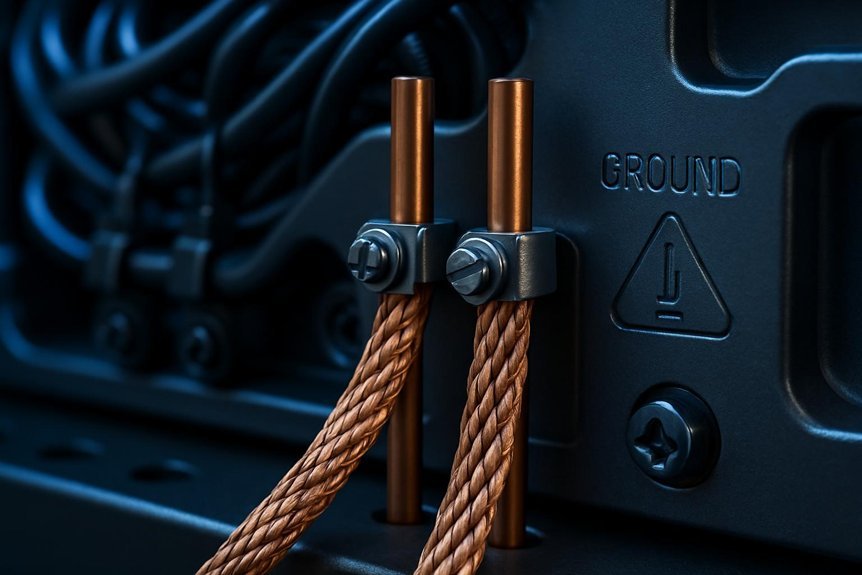
Grounding is more than a safety checkbox—it’s the defined path for fault current and transient energy to return safely to the earth. We begin by clarifying grounding basics: the system’s reference point, earth conductors, and equipment grounding conductors form a low-impedance path that minimizes shock risk and equipment damage. Key concepts include fault current pathways, potential rise, and the importance of proper connectivity to earth electrodes. We differentiate grounding from bonding, noting that bonding enhances metallic convergence without altering the return path’s impedance. We emphasize measurable impedance, clear fault loops, and continuity verification as ongoing safety practices. Our approach keeps installations predictable under fault conditions, ensuring rapid energy dissipation. Readers gain a precise framework for maintaining safe, reliable high-capacity charging environments.
Protective Grounding and Bonding for Safety

Protective grounding and bonding act as the final safeguards that ensure fault currents and transient energy are directed away from people and equipment. We approach this topic with a systematic mindset: verify solid conductor paths, ensure low-impedance routes, and confirm continuous bonding between enclosures, frames, and earth. Our method emphasizes fault-clearing speed, minimized touch hazards, and predictable response to dielectric faults. We evaluate installation practices for integrity, including proper sizing, secure connections, and avoidance of corrosion-prone joints. Grounding etiquette guides safe interaction with utilities, inspectors, and maintenance crews, reducing missteps that compromise safety. Bonding aesthetics, while less technical, influence inspection discipline and corrosion resistance, reinforcing consistent, traceable safety behavior. Together, these principles strengthen resilience, clarity, and compliance in high-capacity charging environments.
Fault Protection Strategies for Large-Scale Charging Stations
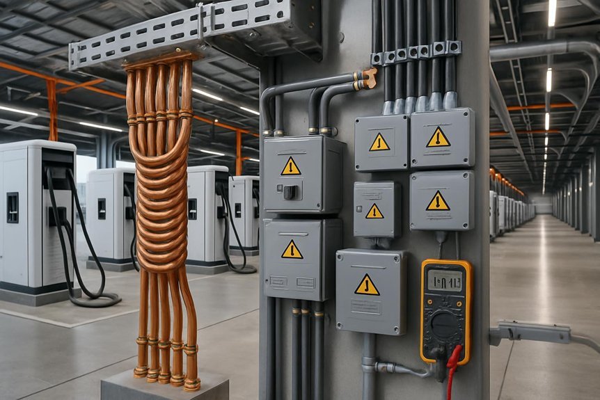
We examine fault isolation techniques and protective relay schemes as core elements of our fault protection strategy for large-scale charging stations. By integrating timely isolation with robust relay coordination, we minimize arc flash risk, equipment damage, and unplanned outages. Our focus is on precise implementation, clear fault signaling, and verifiable fail-safe operation across all charging infrastructure.
Fault Isolation Techniques
What concrete measures ensure system integrity when faults occur in high-capacity charging stations? We implement fault isolation to limit fault effects to the smallest zone possible, preserving downstream operations and personnel safety. Our approach combines coordinated sectionalization, fast-acting disconnections, and validated fault paths that predefine safe de-energization sequences. We design interfaces to prevent fault propagation, using segregated power rails, mechanical and electrical interlocks, and clearly labeled isolation points. Fault containment relies on robust enclosure integrity, selective grounding, and verified isolation through periodic testing and simulation. We document clear recovery procedures, minimize exposure time for staff, and maintain fault history for trend analysis. We prioritize timely fault detection, deterministic responses, and auditable evidence that containment and isolation actions meet fault protection objectives.
Protective Relay Schemes
Can protective relay schemes reliably detect and interrupt faults in large-scale charging stations without compromising uptime or safety? We answer yes, with robust coordination, fast sensing, and selective tripping to minimize disruption. Protective relay architectures enable fault isolation by combining directional overcurrent, differential, and ground-fault components, calibrated to station topology. We emphasize redundancy, metering accuracy, and communication integrity to prevent nuisance trips and ensure rapid isolation when needed. The goal is to maintain continuous service while preserving safety margins, equipment health, and arc-flash risk reduction. A disciplined scheme review documents coordination, trip classes, and maintenance intervals. Table below visualizes operator priorities and relay actions across fault scenarios.
| Fault Scenario | Relay Action/Timing |
|---|---|
| Phase-to-phase | Immediate selective trip |
| Phase-to-ground | Ground-fault clearance |
| Series path fault | Differential isolation |
| High-impedance fault | Monitoring-based hold |
| Communication loss | Safe fallback trip |
Leakage Current Monitoring: Detect Faults Early
We implement continuous leakage monitoring to detect faults early, ensuring we catch anomalies before they impact safety or uptime. By focusing on early fault detection, we reduce risk and enable timely corrective actions. This discussion centers on continuous monitoring as a core safety measure for high-capacity charging systems.
Early Fault Detection
Early fault detection is essential for high-capacity charging systems, and leakage current monitoring provides a practical means to spot insulation degradation or insulation faults before they escalate. We approach this with a structured safety mindset, aligning monitoring thresholds to real-world fault progression and reducing nuisance alarms. By analyzing leakage trends, we identify abnormal paths and preempt cascading faults, preserving personnel safety and system uptime. We also challenge grounding myths and charging myths that obscure true fault signals, ensuring transparent diagnostics and actionable responses.
- Establish baseline leakage profiles for installed gear and update them after alterations.
- Use differential and relay-based checks to confirm anomalies, avoiding false positives.
- Correlate leakage data with environmental and load changes to validate fault progression.
Continuous Leakage Monitoring
How can continuous leakage monitoring elevate fault detection in high-capacity charging systems? We examine leakage patterns to identify insulation degradation before faults manifest. Our approach relies on continuous monitoring of leakage currents under normal operating conditions, enabling rapid recognition of deviations that signal compromised insulation integrity. We interpret small, persistent current shifts as early warnings, guiding targeted inspections and maintenance actions rather than reactive fixes. By establishing baseline signatures for each charger module, we can distinguish harmless transients from actionable anomalies, reducing false alarms and downtime. This discipline enhances safety by catching insulation integrity issues before arcing or shocks occur. We emphasize robust sensor placement, reliable data logging, and clear escalation criteria for remediation.
Arc-Fault Detection: Prevent Fires and Equipment Damage
Arc-fault detection is essential because hidden arcing can ignite insulation or melt conductors before a circuit breaker trips. We approach arc fault risk with precise monitoring, fast signaling, and validated thresholds to minimize exposure. Our goal is robust fault detection that reduces fire potential and equipment damage while maintaining system uptime. By analyzing waveform signatures and impedance changes, we distinguish nuisance events from real faults, enabling targeted intervention. Early warning allowlists and trending help us prioritize maintenance, verify protection coordination, and enforce fire prevention standards. We design for high-capacity charging environments where transient loads and diverse cables complicate protection. Regular testing ensures detectors respond within required timeframes, sustaining safety without unnecessary disconnections.
- Continuous monitoring of arc signatures and trip curves
- Calibration, testing, and fault trend analysis
- Clear escalation and documentation procedures
Grounding System Design for Hubs and Fleets
Grounding system design for hubs and fleets builds on reliable fault detection to ensure safe, continuous operation across high-capacity charging deployments. We assess how the grounding system integrates with fixed infrastructure, distributed loads, and fleet charging patterns to minimize impedance, prevent stray currents, and reduce touch and step hazards. Our approach prioritizes solid conductor sizing, accessible bonding points, and clear labeling to support rapid fault localization. We emphasize hub compatibility, ensuring connection standards align with vehicles, chargers, and safety devices, so equal protection is delivered across all units. We design for fault-current path clarity, robust mechanical integrity, and corrosion resistance in outdoor environments. By detailing these elements, we enable predictable responses to faults while preserving uptime and personnel safety.
Testing and Commissioning Protocols: Steps and Standards
Original Text (word-for-word):
“Effective testing and commissioning ensure high-capacity charging systems perform safely from day one. We approach this phase analytically, defining scope, criteria, and acceptance limits before hands-on work. Our goal is reproducible results that prove safety and reliability under real-world conditions, including fault and load variations. We emphasize rigorous documentation, traceable measurements, and risk-based sequencing. Calibration procedures are applied to protect measurement integrity, verify responses, and confirm system coordination with protective relays. We also plan for outage scenarios, ensuring safe isolation, contingency procedures, and clear communication channels during interruptions. Acceptance criteria reflect standards compliance, manufacturer guidance, and site-specific hazards. Our structured approach minimizes rework and accelerates commissioning while safeguarding personnel and equipment.
Effective testing and commissioning ensure safe, reliable high-capacity charging systems from day one.
- Define scope, criteria, and safety acceptance thresholds
- Validate instrumentation, protections, and control logic
- Verify performance under planned outage scenarios and post-event recovery”
Ongoing Maintenance and Diagnostics
Ongoing maintenance and diagnostics keep high-capacity charging systems safe and reliable after commissioning. We approach this with disciplined, data-driven checks that verify electrical integrity, insulation resistance, and grounding continuity under varying load conditions. Our routine prioritizes rapid fault isolation, trend analysis, and preventive replacement schedules to minimize unplanned outages. We document observations, calibrations, and test results to build a continuous performance profile, supporting risk-informed decision making. Maintenance actions align with a disciplined integration of subsystem health indicators, ensuring that protective relays, interlocks, and fault annunciation remain coordinated across modules. Our procurement strategy emphasizes component provenance and compatibility, reducing obsolescence risk while preserving safety margins. We emphasize clear escalation paths and traceable records to sustain compliance, safety culture, and system resilience.
Compliance, Standards, and Documentation You Can Trust
How do we ensure compliance, standards, and documentation you can trust in high-capacity charging systems? We approach this with rigorous verification, traceable records, and explicit safety criteria. Our method minimizes ambiguity by aligning with recognized frameworks, conducting objective assessments, and maintaining transparent documentation to support audits and incident reviews. We focus on controlling risk through consistent procedures, clear responsibilities, and timely updates that reflect evolving regulations. We acknowledge that unrelated topic ideas and irrelevant concepts can creep into planning; we filter them out to preserve technical integrity. This discipline is essential for reliability, failsafe operation, and credible certification.
- Establish traceable compliance pathways and versioned standards
- Document test results, configurations, and corrective actions
- Regularly review governance to prevent drift and ensure safety continuity
Frequently Asked Questions
How Does Grounding Interact With Energy Storage Safety Margins?
Grounding interaction shapes energy safety margins by providing defined fault paths, enabling rapid fault clearing and clamp-down of transient voltages. We, hence, assess, test, and document margins to ensure robust energy safety under fault conditions.
What Are Practical Indicators of Degraded Bonding Performance?
We observe degraded bonding by corrosion, loose connections, and increasing impedance during routine bonding inspection; practical indicators include intermittent grounding faults, elevated earth-signal noise, and delayed fault clearing. We emphasize grounding maintenance and bonding inspection for safety.
Can Leakage Current Monitoring Detect DC Faults in HV Systems?
Yes — leakage monitoring can detect dc faults in a charging system; we routinely analyze leakage signals for hv safety, fault timing, and isolation integrity, ensuring early dc fault detection and prompt remediation.
How to Justify Grounding Upgrades for Fleet Expansion?
We’ll demonstrate grounding upgrades as essential for fleet expansion, dramatically reducing risk and downtime. Our analysis shows safer fault clearance and reliability gains, confirming that grounding upgrades are critical as we scale to meet fleet expansion demands.
What Are Cost-Effective Methods to Verify Arc-Fault Coverage?
We can verify arc-fault coverage cost-effectively by performing targeted testing and monitoring, ensuring bonding impedance stays within spec; this confirms arc-fault coverage and minimizes nuisance trips, improving safety while sustaining reliable operation.
Conclusion
We’ve emphasized that robust grounding, continuous bonding, and fast-acting fault isolation are the backbone of safe, reliable high-capacity charging systems. By monitoring leakage and arc faults, we detect issues before they escalate, protecting people and equipment. Think of our safety architecture as a shielded bridge: each component must resist and route fault current decisively. With disciplined testing, maintenance, and documentation, we guarantee compliant, durable operation and rapid fault clearance for fleets and hubs alike.