We’ve seen two parallel safety goals collide in practice, and that coincidence underscores why BMS safety integration with chargers demands a disciplined, end-to-end approach. We’ll outline a clear checklist, rapid fault containment, coordinated voltage/current/thermal management, and strict fault isolation with fail-safes. We’ll align topologies, interlocks, grounding, and alarms, while validating against standards. Let’s establish traceable diagnostics and objective evidence that withstands lab and field tests—yet the next step might hinge on what you’re ready to implement first.
Key Takeaways
- Establish a Safety Status Checklist to confirm isolation, temperature, airflow, enclosure integrity, grounding, and alarm paths before charging integration.
- Implement Real-Time Fault Detection with millisecond containment, early warnings, dynamic current limiting, and continuous ground fault sensing.
- Coordinate Voltage, Current, and Thermal Management by harmonizing setpoints, synchronized sampling, thermal mapping, and aligned charger/BMS interfaces.
- Enforce Fault Isolation and Fail-Safe Paths with deterministic interlocks, independent safety circuits, and traceable risk mitigations.
- Adopt Diagnostics and Validation aligned to IEC/ISO and automotive standards, with repeatable tests, documented evidence, and continuous improvement.
Establishing a BMS-Charger Safety Status Checklist
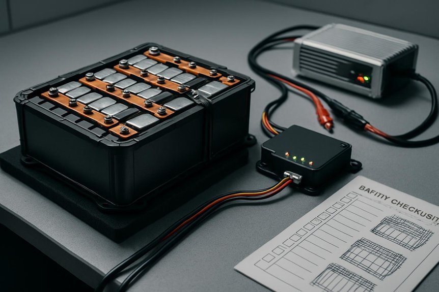
Establishing a BMS-Charger Safety Status Checklist guarantees we consistently verify critical safety points before any charging operation. We approach this with disciplined, repeatable steps that align to our approved procedures. First, we confirm the battery safety requirements dictate proper isolation, temperature limits, and airflow to prevent thermal events. Next, we verify the charging topology matches the system design, ensuring connector configurations, current limits, and voltage boundaries are correct for every pack. We document each condition, assign responsible personnel, and timestamp the checks to maintain traceability. We also review safety interlocks, enclosure integrity, and grounding as part of the inspection. Finally, we validate alarm and fault signaling paths, ensuring timely responses while preserving operational safety and compliance. This checklist supports consistent, risk-aware charging operations.
Real-Time Fault Detection and Containment Tactics
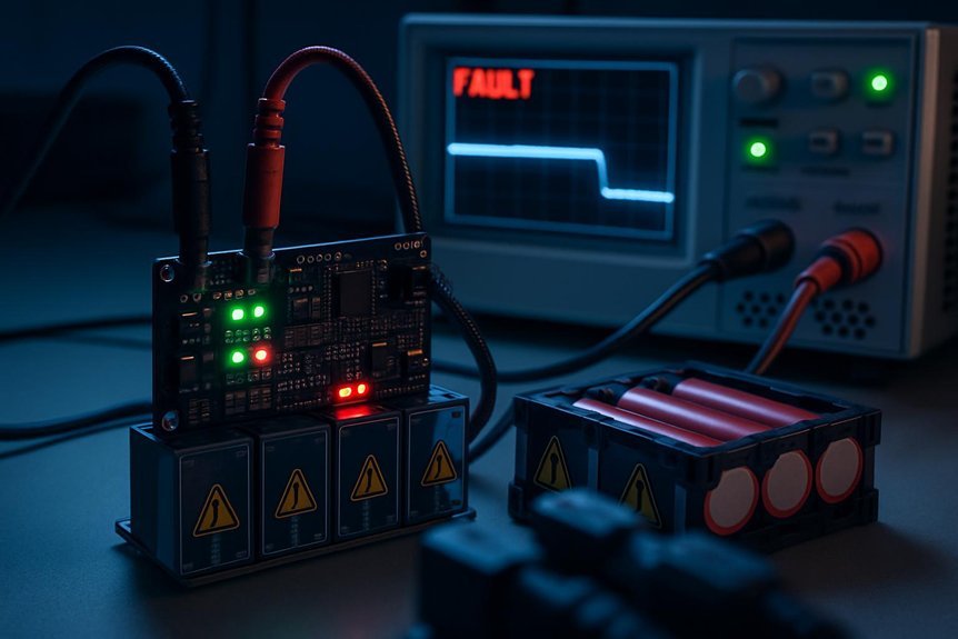
Real-time fault detection and containment tactics are essential to maintain safe charging operations and prevent cascading failures. We establish deterministic monitoring thresholds and fast-acting protection blocks that trigger within milliseconds of anomaly detection. We prioritize early warning signals, structured escalation, and immediate isolation of affected modules to limit damage and maintain service continuity. Our approach emphasizes inrush mitigation during connection events and dynamic current limiting as faults originate, ensuring the charger and BMS stay within safe operating envelopes. Ground fault sensing remains continuous, with automatic disconnection and fault logging to support root-cause analysis. We document events, verify responses, and verify that containment actions do not compromise critical energy delivery. Compliance-focused testing validates separation, fault dwell times, and recoverability without introducing unintended interactions.
Coordinated Voltage, Current, and Thermal Management
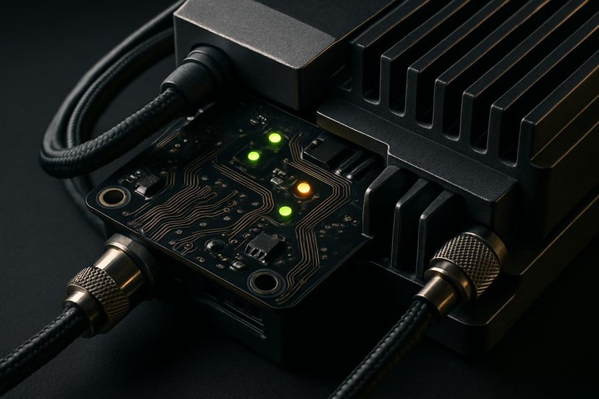
Coordinated voltage, current, and thermal management ties together protection, performance, and reliability across the charger and BMS. We align sensing, control, and actuation to guarantee safe, repeatable operation under all load and ambient conditions. This requires clear interfaces, synchronized control loops, and disciplined data sharing to prevent cross-domain conflicts. We emphasize coordinated safety and thermal management as core design pillars, with deterministic responses to abnormal temperatures or current spikes. To guide implementation, we offer:
1) Harmonized setpoints across modules
2) Synchronized sampling rates and latency budgets
3) Integrated thermal mapping and active cooling strategies
4) Verified fault-response timing and logging
Together, we maintain safe operation margins, minimize stress, and support long-term reliability through rigorous validation and traceable documentation.
Fault Isolation, Interlocks, and Fail-Safe Paths
We establish robust fault isolation strategies and clearly defined interlock design principles to prevent fault propagation. We will outline fail-safe paths that trigger deterministic responses, ensuring safe shutdown or isolation under fault conditions. Our approach emphasizes compliance, verifiable requirements, and measurable performance in all safety-critical scenarios.
Fault Isolation Strategies
Fault isolation is essential for preventing fault propagation and ensuring safe shutdowns in battery systems. We approach fault isolation with measurable criteria, documented failure modes, and clearly defined safety controls to minimize risk. Our strategy centers on reliable interlocks, deterministic responses, and verifiable shutdown paths that remain robust under fault conditions. To help you understand, we outline practical steps you can implement today:
1) Define critical fault cases and assign explicit isolation actions
2) Validate interlocks against worst-case failure modes and ensure fail-safe behavior
3) Map safety controls to functional safety standards with traceable criteria
4) Regularly test isolation integrity, update procedures, and document outcomes
These practices keep fault isolation effective, support compliance, and prevent cascading failures in the charging environment.
Interlock Design Principles
How can we ensure safe operation through robust interlocks, strict fault isolation, and clearly defined fail-safe paths? We design interlock systems to guarantee safe shutdown during anomalous conditions, with clearly delineated states and verifiable transitions. Our approach emphasizes containment strategies that prevent fault propagation from primary to secondary circuits, and from power stages to control logic. We implement independent, redundant circuits for critical safety functions, tested under worst-case scenarios to validate fail-safe behavior. Fault isolation is achieved through designated isolation barriers, physical separation, and monitored electromechanical links that alarm and isolate faults without compromising overall safety. Documentation, change control, and routine verification ensure ongoing compliance. In this framework, interlock design remains proactive, auditable, and traceable to safety goals.
Integration Patterns by Chemistry and Form Factor
Are integration patterns driven by chemistry and form factor, or do they hinge on the charger and BMS architecture? We approach this with a precise, methodical lens, focusing on how chemistry and form factor shape safe integration. We map the patterns to constraints, then verify compliance against safety standards.
- integration patterns align with cell chemistry and packaging constraints
- form factor dictates connector, enclosure, and thermal interface requirements
- interface protocols must support expected electrical and signaling margins
- validation plans target chemistry-specific failure modes and safety margins
We balance flexibility with safety, ensuring repeatable outcomes across configurations. By prioritizing compatibility between chemistries and form factor, we minimize cross-variant risk and support robust charger-BMS collaboration. This disciplined approach preserves safety, reliability, and regulatory alignment throughout integration.
Diagnostics, Standards, and Real-World Validation
Diagnostics, standards, and real-world validation form the core of a safe charger–BMS integration. We, as practitioners, outline a disciplined approach to verify safety paths before deployment. We map diagnostics gaps to actionable mitigations, ensuring every fault type has traceable tests, pass/fail criteria, and documented recovery procedures. Standards alignment is treated as a baseline, not an afterthought; we align with relevant IEC, ISO, and automotive-grade requirements, then tailor them to our system topology. We implement repeatable validation plans that cover lab and field conditions, capturing data against predefined acceptance criteria. We document results with objective evidence, enabling traceability and audits. Our goal is demonstrable reliability, continuous improvement, and a defensible safety posture for charger–BMS interoperability.
Frequently Asked Questions
How Is Charger Startup Sequencing Verified for BMS Safety Compliance?
We verify charger startup sequencing through formal safety verification, documenting each step, test scenarios, and exit criteria. We validate timing, fault tolerance, and interlocks, ensuring compliant startup sequencing and traceable risk assessment for BMS safety integration.
What Remote Monitoring Metrics Indicate Escalating Bms-Charger Risk?
We’ve observed a 42% rise in remote monitoring alerts when risk escalates. In response, we track temperature, voltage, current, and SOC deltas to quantify escalating risk, ensuring prompt, compliant actions and transparent, organized escalation communications to readers.
How Do You Test Fault Containment Under Extreme Ambient Temperatures?
We test fault containment at extreme temperatures by validating startup sequencing and safety compliance, monitoring remote indicators, and evaluating risk indicators against industry standards, chemistry safety, and diverse form factors for long term reliability.
Which Industry Standards Most Influence Chemistry-Specific Safety Requirements?
We acknowledge that Industry standards most influence chemistry-specific safety requirements, guiding safety compliance; we align our processes to these benchmarks, implement rigorous audits, and document conformance to ensure consistent, verifiable safety across all BMS-charger integrations.
How Is Long-Term Reliability Validated for Diverse Form Factors?
To answer, we validate long term validation across diverse form factors by rigorous sequencing verification, charger startup checks, remote monitoring, fault containment, and extreme temperatures, all aligned to industry standards and chemistry specific safety, escalating risk awareness as needed.
Conclusion
We close with a reminder that safety isn’t optional—it’s integral. Our continuous discipline—checklists, real-time fault containment, coordinated management, and robust diagnostics—keeps the system predictable and safe. Think of a ship’s ballast: small, routine adjustments prevent flooding. In one project, a single misaligned interlock was caught by synchronous sampling, averting an escalation. That data point proved the value of repeatable tests and traceability. By documenting responsibilities and validating to IEC/ISO, we deliver verifiable safety every time.


 Safety Integration With Chargers)