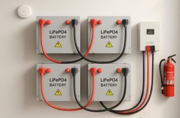
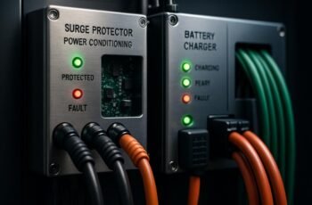
We must prevent connector arcing and short circuits during charging by enforcing clean, dry contacts, proper insulation, and secure mating. We’ll emphasize correct ratings, robust strain relief, and continuous monitoring of contact resistance, temperature, and environment. Our approach combines proactive inspection, disciplined maintenance, and thorough documentation to sustain arc-free charging. We’ll outline practical checklists and actionable steps, but the specifics you’ll need to implement carefully may surprise you—and what we uncover next is essential for safer, reliable operation.
Key Takeaways
- Ensure clean, secure connections with properly rated cables and connectors; replace worn or damaged parts to minimize contact resistance and arcing risk.
- Maintain proper alignment, mating, and insulation integrity; avoid partial mating, sharp bends, and flexing that damage cables.
- Implement clean routing and adequate separation of power, data, and communication lines to reduce cross-talk and arcing potential.
- Use continuous fault monitoring (current, voltage, temperature, impedance) with redundant sensors at critical joints for early detection.
- Enforce thorough inspection, cleaning, storage, and handling protocols to prevent contamination and moisture at interfaces.
What Causes Arcing and Short Circuits During Charging
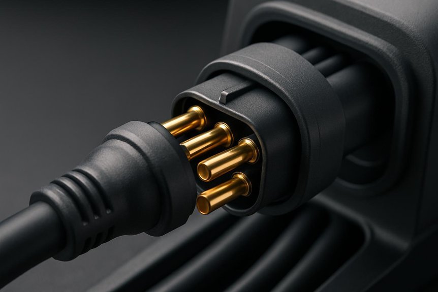
What exactly causes arcing and short circuits during charging? We start by examining contact quality, insulation integrity, and lead routing, since small gaps can ionize under high voltage and current. Poor connections, worn or damaged connectors, and contaminated surfaces raise contact resistance, generating localized heating and plasma that initiates an arc. Misalignment or partial mating increases electric field stress, while bending or excessive flexing damages insulation, creating leakage paths. External moisture, dust, or conductive debris lowers breakdown voltage and promotes shorting, especially at connector interfaces. System design factors, like improper current ratings or inadequate protection, exacerbate risk. To reduce risk, practice arc prevention through clean, dry surfaces, validated mating procedures, and regular connectors inspection as part of a robust safety program.
How to Inspect Chargers and Connectors for Early Faults
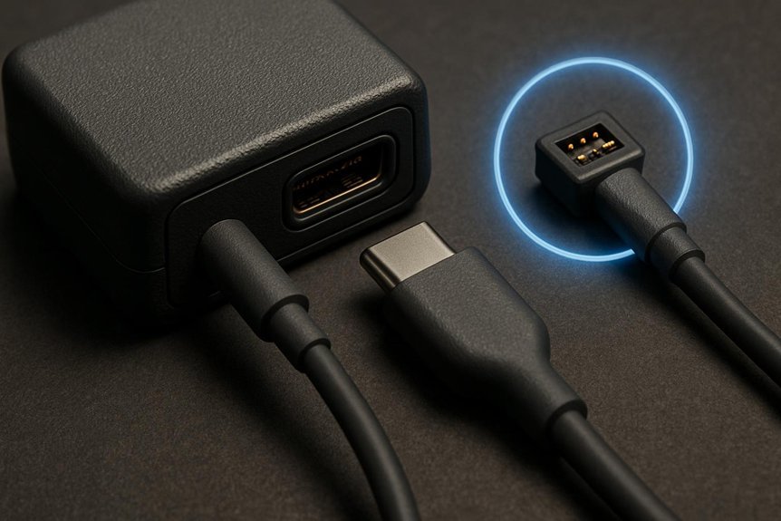
We inspect chargers and connectors for early faults by assessing wear, ensuring contacts remain clean, and verifying mating surfaces for uniform contact. We test for contact resistance and document any drift that could indicate loosening or heat hotspots. We’ll spot early fault signs—misalignment, corrosion, chafed cables, and damaged seals—to prevent arcing and short circuits during charging.
Inspecting Connector Wear
Are you regularly checking for wear on charging connectors to prevent faults before they escalate? We, the team, inspect connector wear with a methodical, safety-focused approach that prioritizes immediate risk reduction and clear documentation. We follow strict safety protocols and observe every tactile and visual cue for degradation.
- Inspect contact surfaces for pitting, grooves, or discoloration.
- Check insulation and housing for cracks, looseness, or deformation.
- Verify connector retention and cable strain relief under load and flex.
We record findings, tag suspect components, and replace when thresholds are reached. This proactive routine minimizes arcing risk and ensures ongoing reliability. By adhering to these steps, we maintain connector wear awareness and uphold safety protocols that protect personnel and equipment.
Testing for Contact Resistance
Do we really understand a connector’s health just by looking at it? We know that visual cues can hide latent faults, so we test contact resistance to verify integrity under load. We measure with calibrated instruments, observe contact stability, and compare against manufacturer tolerances. A high resistance indicates poor contact, excessive heating, and potential arcing risk. We document results, noting variations between connectors of similar type, and assess whether insulation integrity remains intact around terminations. We also evaluate connector polarization to guarantee proper alignment and contact mating. If resistance drifts with temperature or cycling, we flag replacement and rework promptly. Safety remains our priority, and consistent testing procedures reduce fault propagation during charging.
| Test Point | Expected Range | Action if Out of Spec |
|---|---|---|
| Contact resistance under load | Low, stable | Replace or reseat |
| Temperature rise | Minimal | Stop, inspect insulation integrity |
| Polarization check | Correct orientation | Correct wiring, verify |
| Connection damping | Low noise | Re-torque, clean contacts |
Spotting Early Fault Signs
Spotting early fault signs starts with a practical, eyes-on approach to chargers and connectors. We inspect for heat, corrosion, wear, and loose fittings, then verify dimensions and tolerances align with charging protocols. Early signs point to degraded insulation, bent pins, and arcing indicators; documenting these helps prevent escalation. We emphasize connector ergonomics to reduce handling stress and misconnection. Systematically, we compare observed conditions to baseline data and manufacturer specs.
- Inspect contact surfaces, insulation health, and pin alignment against standards and prior readings.
- Check for abnormal temperature rise, cracking, or discoloration during a low-load test and note any hesitation or resistance.
- Confirm cable strain relief, housing integrity, and secure locking mechanisms before initiating charging protocols.
Choosing Cables, Connectors, and Ratings for Safe Charging
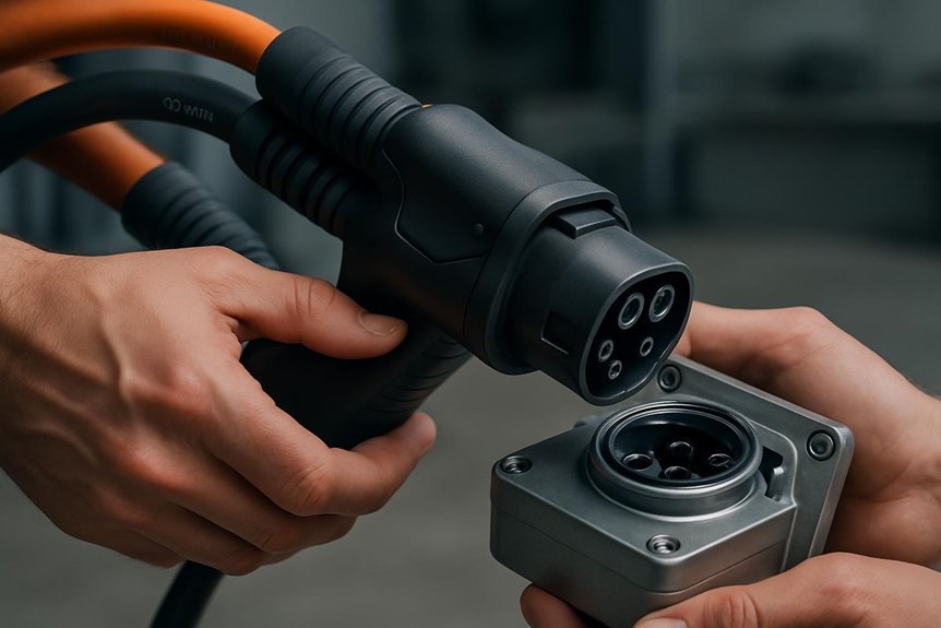
We’ll start by selecting cables with appropriate gauge to handle the expected current without overheating or voltage drop. We’ll verify connector ratings to ensure they meet system demands and maintain a safe contact interface under charging conditions. We’ll confirm that voltage requirements match both the power source and the device, preventing mismatches that could lead to arcing or short circuits.
Cable Gauge Matters
Selecting the right cable gauge is essential for safe charging, as it directly affects current capacity, voltage drop, and heat generation. We emphasize precise sizing to minimize arcing risk and maintain system integrity. Key considerations include insulation rating, conductor material, and permissible operating temperature.
- We specify continuous current rating to prevent overheating and voltage loss.
- We verify insulation and connector compatibility to reduce arcing paths.
- We select gauge that matches charging profile and connector ratings for safe operation.
Connector Rating Safety
Connector ratings tie together cable capability, connector hardware, and charging profiles to prevent arcing and shorts. We choose cables with adequate amperage, voltage, and insulation margins, ensuring the conductor cross-section matches expected load. Connector hardware must meet current standards, with secure latching, robust contact surfaces, and proper shielding to minimize exposure during coupling and disconnection. We evaluate compatibility between the charger, cable, and inlet, confirming temperature rise remains within safe limits under worst-case duty. Clear rating documentation guides safe pairing and maintenance schedules. We emphasize connector safety by inspecting pins for wear, avoiding damaged housings, and replacing components with exact or higher ratings. This disciplined approach reduces arc exposure, supports predictable charging, and reinforces overall system safety during plug-in operations. Arc prevention remains our primary objective.
Matching Voltage Requirements
How do we guarantee voltage compatibility across the charging path to prevent risk of insulation breakdown or arcing? We assess system voltage, conductor rating, and connector phasing to ensure all components share the same voltage class and phase alignment. Mismatches elevate heat, stress insulation, and risk arcing, so precise matching matters. We implement strict verification of voltage rating, insulation clearance, and protective interlocks before each charge.
- Verify Voltage Compatibility: confirm supply, cable, and connector ratings align with the charging protocol.
- Confirm Connector Phasing: ensure phase order and grounding are correct to prevent cross-phase faults.
- Validate Ratings End-to-End: inspect insulation, creepage, and amperage limits for safe continuous operation.
The 5-Minute Pre-Charge Check: Cleanliness and Tight Connections
Have you double-checked the connector surfaces and terminal pins? We perform a brisk five-minute pre-charge check to prevent arcing and misalignment. First, we inspect contact faces for contamination, corrosion, or residue, confirming clean surfaces before any connection. Next, we verify that all pins and receptacles seat fully without tilt or gap, noting any deformation. We then execute cleanliness routines to remove dust, oil, or oxidation using manufacturer-approved wipes and solvents, applied with controlled, non-abrasive motions. Finally, we confirm connector tightening to specified torque, rechecking fasteners, latches, and clamps for secure engagement. This disciplined sequence minimizes resistance peaks and heat generation during initial current flow. We document results and replace any suspect components before charging.
Safe Storage and Handling to Prevent Hidden Damage
We store and handle connectors with designated, clean, and dry conditions, following Safe Storage Practices to minimize hidden damage. Before any handling, we Inspect Before Handling to verify integrity and cleanliness, ensuring there are no signs of corrosion or wear. Proper Connector Storage is mandatory, using sealed, labeled containers and protected, upright placement to prevent physical damage and contamination.
Safe Storage Practices
Safe storage practices are essential to prevent hidden damage that can compromise charging safety. We prioritize controlled environments, Routine checks, and disciplined handling to minimize arcing prevention risks and maintain storage hygiene.
- We store components in clean, dry enclosures, away from conductive surfaces and heat sources.
- We label and inventory items, terminating exposure to dust and moisture while ensuring cable ends remain capped.
- We implement periodic verification, recording conditions and inspecting for signs of corrosion, swelling, or deformation.
Inspect Before Handling
Before handling any component, we verify its condition to prevent hidden damage from storage. We inspect for insulation degradation and signs of connector fatigue that storage can induce. We confirm there are no pin bends, corrosion, or loose housings, and we test continuity where applicable. If anything appears compromised, we quarantine the item and document the issue before proceeding. Handling is performed with clean, dry gloves and tools rated for electrical work to avoid further damage. Gentle tactile checks replace forceful manipulation, ensuring seals, gaskets, and locking mechanisms are intact. We log the inspection results and reference maintenance schedules to sustain reliability. Visual table below summarizes key checks.
| Check | Indicator | Action |
|---|---|---|
| Inspect insulation | Discoloration, cracking | Replace if damaged |
| Inspect contacts | Pitting, corrosion | Clean or replace |
| Mechanical fit | Wobble, looseness | Tighten or replace |
| Locking mechanisms | Stiffness, wear | Service/replace |
| Documentation | Sign-off | Record findings |
Proper Connector Storage
How can we ensure connector storage minimizes hidden damage and preserves reliability? We implement disciplined, repeatable storage practices that protect contacts, housings, and seals while enabling rapid, safe reassembly. Key considerations include ergonomic handling, material compatibility, and documented risk assessment.
- Store connectors in designated, clean bins with labeled orientation to preserve connector ergonomics and prevent misalignment.
- Protect ends with caps or covers, ensuring moisture and dust exclusion while maintaining correct polarity and seating depth.
- Log storage conditions and inspection results, updating risk assessment periodically to detect evolving hazards and to guide preventive maintenance.
These steps reduce latent damage, support traceability, and sustain charging system reliability through careful organization and COTS-standard safety controls.
Environmental Factors That Elevate Arcing Risk
Environmental factors substantially raise arcing risk during charging. We, as practitioners, analyze how ambient conditions influence connector integrity and current pathways. Temperature extremes can alter insulation strength and material creep, increasing leakage potential and arcing risk at contact interfaces. Humidity and condensation raise surface conductivity, promoting unintended current paths across housings and seals. Dust, salt spray, and chemical vapors degrade connectors, creating conductive contaminants that concentrate at contact points. Vibration and mechanical shocks loosen connections, widening gaps and fostering transient arcs during plug-in or disconnect cycles. Altitude and air pressure shifts affect cooling efficiency, potentially elevating junction temperatures and arc support. We emphasize monitoring environmental factors, enforcing rated environmental specs, and selecting components designed for anticipated conditions to minimize arcing risk.
Cable Management Best Practices: Routing, Strain Relief, Separation
Cable routing, proper strain relief, and deliberate separation are foundational to maintaining safe, reliable charging systems after addressing environmental arcing factors.
Cable routing, strain relief, and separation ensure safer, more reliable charging systems.
We implement disciplined cable management to minimize stress, heat buildup, and unintended contact. Our approach emphasizes repeatable, verifiable practices that support safety margins and fault tolerance.
1) Routing geometry: prefer clean, unobstructed runs that avoid sharp bends and pinch points.
2) Strain relief: secure connectors and cables to absorb movement without transmitting load to electrical interfaces.
3) Separation: maintain physical gaps between power, data, and communication lines to reduce cross-talk and arcing potential.
Together, these measures ensure predictable performance and reduce maintenance cycles by preserving insulation integrity and connector contacts under operational loads. Regular inspections verify routing integrity, restraint effectiveness, and separation compliance.
Detection and Monitoring: Tools That Catch Faults Early
Detection and monitoring systems provide early warning of faults before they escalate into failures. We implement continuous sensing across connectors, cables, and interfaces to identify anomalies that precede arcing prevention and short-circuit events. Our approach combines current, voltage, temperature, and impedance metrics with real-time spectral analysis to flag deviations from baseline behavior. We deploy redundant sensors at critical junctions to ensure coverage even under flexing and transient loads. Alerts trigger automated shutdown or isolation, preventing damage and safety hazards. Data logging supports trend analysis, calibration checks, and maintenance planning. We emphasize calibrated thresholds, fail-safe designs, and clear operator guidance. By prioritizing fault detection, we reduce exposure to energized faults and maintain charging-system integrity.
Step-By-Step Troubleshooting for Common Arcing Scenarios
We’ll start from the detection data we’ve gathered and methodically work through common arcing scenarios you’re likely to encounter. When arcing is detected, we triage by fault origin and apply immediate containment, then verify the integrity of the connector lifecycle. Our stepwise approach prioritizes safety and precise corrective actions.
- Validate isolation and power-down, then inspect contact surfaces for pitting, corrosion, or contamination that could reignite arcing.
- Assess cable strain, connector seating, and alignment; reseat or replace compromised halves to restore reliable arcing prevention.
- Test insulation resistance and continuity, updating fault logs to refine maintenance windows and prevent recurrence.
We document results, update procedures, and emphasize compatible components to sustain safe charging.
Preventive Maintenance Routine for Safer Charging Practices
Initiate a structured preventive maintenance routine by scheduling regular inspections, tests, and component replacements to uphold safe charging practices. We outline a formal cadence: visual inspections of connectors, insulation integrity checks, and contact resistance measurements; functional tests for interlocks and charging indicators; and scheduled replacement of worn cables, ferrules, and seals. Our goal is Preventive maintenance that minimizes arcing risk and sustains Safer charging outcomes. Maintain documentation of every finding, action, and revision to enable traceability and accountability. The following imagery illustrates the routine:
| Preventive tasks | Safety outcomes |
|---|---|
| Inspections, tests, replacements | Reduced fault probability, enhanced reliability |
Adhering to this routine preserves system integrity, reduces downtime, and supports ongoing safe operation.
Frequently Asked Questions
How Often Should I Replace Worn Charging Connectors?
We replace worn charging connectors every 1–3 years, depending on usage and inspection results. We continuously emphasize reliability testing and assess supply chain integrity to ensure connectors meet safety standards and performance requirements for safe charging operations.
Can Heat From Charging Degrade Cable Insulation Over Time?
We’ve seen heat cause insulation aging and heat degradation over time, yes. We must monitor temps, limit exposure, and replace worn cables promptly to maintain safety, reliability, and performance during charging, avoiding hidden failures through proactive inspections.
Do IP Ratings Ensure Arc Prevention in All Environments?
We can’t claim IP ratings guarantee arc prevention in all environments. Arc ratings contribute to electrical safety and enclosure protection, guiding energy transfer limits, but environmental factors still demand site-specific testing and proper safety protocols.
What Signaling Indicates Imminent Connector Failure During Charging?
“Face it head-on” — we notice imminent failure indicators via erratic voltage, rising temperatures, and unexpected resistance during charging. Our charging connector diagnostics alert us to anomalies, enabling proactive maintenance before faults escalate and safety is compromised.
Are Wireless or Contactless Charging Options Safer for Arcing Prevention?
Yes, wireless charging reduces arcing risk vs contact plugs; Wireless safety hinges on robust inductive SMTs, tight magnetic coupling, and careful shielding. We favor Contactless charging vs arcing, emphasizing consistent alignment and fault detection to prevent arcing.
Conclusion
Together, we’ve mapped a path to safer charging through vigilant inspection, correct ratings, and disciplined maintenance. When we keep contact surfaces clean, mating aligned, and cables properly rated with robust strain relief, faults drop from sight. Think of our preventive routine as a shield—thin yet unyielding—that wards off arcing and shorts before they spark. By monitoring resistance and temperature, we stay ahead. Stay proactive, document everything, and let safety be the baseline, not an afterthought.