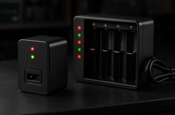
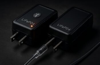
We’re evaluating whether a 3-stage or 4-stage LiFePO4 charger best fits our system’s control granularity and lifecycle trade-offs. The 3-stage approach stays lean—fewer sensors, simpler transitions, lower cost—while the 4-stage adds a refinement that can tighten voltage convergence and thermal management. Each path has impacts on efficiency, maintenance cadence, and BMS compatibility, and the choice will hinge on your specific use case. We’ll weigh these factors as we proceed, and the implications become clearer as we compare practical outcomes.
Key Takeaways
- A 3-stage charger uses CC, CV, and a final termination, while a 4-stage charger adds an additional rest/holding or formation sub-stage for balance.
- A 4-stage design can improve balance convergence and efficiency at higher state-of-charge by more granular control.
- The extra stage raises system complexity, cost, and potential calibration needs versus the simpler 3-stage approach.
- 3-stage systems are typically sufficient for standard LiFePO4 packs; 4-stage suits larger packs or demanding duty cycles.
- Choose based on monitoring precision, BMS compatibility, and maintenance cadence; more stages aid control, less stages reduce risk of faults.
LiFePO4 Charging Basics: What Charging Stages Do
Charging LiFePO4 batteries proceeds through distinct stages that manage voltage, current, and temperature to optimize safety and longevity. We describe the charging process in terms of stages that control energy input while protecting cell chemistry and pack integrity. In practice, stage transitions reflect monitored parameters: voltage thresholds, current decay, and temperature limits. The emphasis is on maintaining battery safety through controlled engagement of each phase, preventing overcharge, overheating, or undue stress. During initial constant-current execution, we push capacity while tracking cell balance signals; as voltage rises, current tapers during constant-voltage regulation to finish balancing and avoid divergence. Firmware plays a crucial role: charger firmware algorithms enforce safe limits, respond to sensor data, and log events for diagnostics. Understanding these stages clarifies why governance of voltage, current, and temperature matters for LiFePO4 longevity.
Three-Stage vs Four-Stage Charging: Which Fits Your Use Case
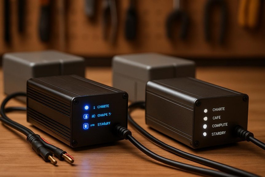
Which charging strategy best aligns with your LiFePO4 application—the classic three-stage approach or the more granular four-stage variant? We present a concise three stage vs four stage comparison to help you select the model that matches your constraints. Our focus is decision relevance: charging profiles, runtime expectations, and system integration trade-offs rather than operational minutiae. In many applications, the three stage vs four stage distinction defines complexity, cost, and control granularity. Consider whether tighter voltage thresholds and staged rest periods improve efficiency for your pack chemistry, or whether simpler control suffices for rugged environments. We evaluate compatibility with existing BMS interfaces and automation goals, ensuring the chosen strategy aligns with monitoring precision, thermal management, and maintenance cadence.
How Each Stage Works in Practice for LiFePO4
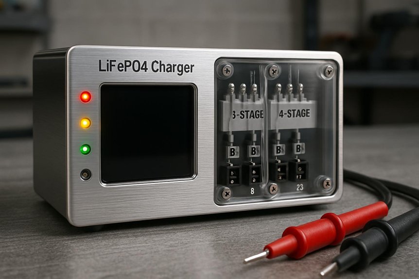
We examine how Stage Charge Behavior unfolds in LiFePO4 systems, focusing on current, voltage thresholds, and transition timing to reflect real-world performance. Our discussion highlights LiFePO4 charging dynamics, including how impedance, phase durations, and termination criteria influence efficiency and cell balance. We invite you to consider how these practical nuances shape the trajectory of each charging stage and its impact on longevity and safety.
Stage Charge Behavior
Stage charging for LiFePO4 unfolds in a sequence of distinct, tightly controlled steps that optimize voltage, current, and cell balance. In practice, we monitor each stage’s thresholds, ensuring current tap-down and voltage ceilings are respected to prevent overcharge. During formation, cells rise to the target voltage with controlled slope, then hold to equalize capacity while current decays toward termination. In endurance stages, the charger sustains a small current to compensate self-discharge and parasitic losses without stressing cells. We prioritize a reliable battery profile by balancing convergence speed with thermal limits, avoiding oscillations that degrade longevity. The cost comparison informs our controller choices: more stages can improve efficiency and balance, but complexity and component quality drive total expense. Overall, precise stage management yields safer, longer-lasting LiFePO4 packs.
Lifepo4 Charging Dynamics
Charging dynamics for LiFePO4 hinge on how each stage governs voltage, current, and time to shape a safe, efficient profile. We approach this by detailing practical behaviors of each phase and their implications for real-world use. In constant-current phases, we push C-rate targets until nearing cutoff, ensuring controlled heat generation and monitoring for voltage limits. Transition to constant-voltage stages emphasizes tight voltage regulation, balancing charge acceptance with temperature checks to prevent plate degradation. We track end-of-charge indicators, like taper currents, to minimize overfill risks. Throughout, we assess battery safety implications, including protection against overvoltage, short circuits, and thermal runaway scenarios. For solar integration, we consider sun variability, module constraints, and how staged charging mitigates impedance shifts. Overall, dynamics optimize efficiency, longevity, and reliable performance.
Practical Tips to Maximize Cycle Life With Either Setup
Practical tips to maximize cycle life with either setup require disciplined charging and operation practices that minimize stress on the LiFePO4 cells. We implement a Two Stage Charge Method to reduce unnecessary current during rest and to control voltage rise, thereby preserving electrolyte balance and electrode integrity. Maintain a strict charge window: avoid charging beyond 3.65 V per cell in any stage, and ensure timely termination to prevent overpotential fatigue. Use balanced charging to equalize cells and monitor temperature; excessive heat accelerates degradation. Prefer moderate C-rates aligned with manufacturer guidance, and allow shallow cycles when feasible to reduce depth of discharge stress. Document cycle counts and revise profiles seasonally. Finally, ensure charger firmware and BMS settings align with LiFePO4 chemistry to sustain consistent, long-term performance.
When to Troubleshoot: Common LiFePO4 Charging Issues
What signals suggest something’s wrong with LiFePO4 charging, and how do we diagnose them quickly and accurately? We systematically observe voltage, current, temperature, and charge time against spec sheets. Anomalies like prolonged constant-current charging beyond expected duration, premature voltage knee, or unfinished absorption indicate a fault. We verify with a known-good test pack and an identical charger to isolate the culprit. We inspect wiring for loose connections, damaged insulation, and degraded contacts, and we confirm the charger’s output within its rated tolerance. Temperature spikes during charging reveal internal resistance or cell balance issues, which require safety checks before attempting further charging. We prioritize lithium safety and assess charger durability, ensuring enclosures, fuses, and isolation meet standards. If issues persist, halt charging and re-evaluate safety margins.
How to Optimize Efficiency and Maintenance Over Time
We’ll outline clear paths for Efficiency Preservation Tips, Maintenance Scheduling Strategies, and Longevity Optimization Techniques to keep LiFePO4 chargers performing at peak over time. By analyzing usage patterns, environmental factors, and component wear, we’ll quantify impacts and establish concrete, repeatable practices. Our goal is to provide precise actions readers can implement now to sustain efficiency and reliability.
Efficiency Preservation Tips
Maintaining high efficiency over the life of a LiFePO4 charger hinges on disciplined monitoring and proactive management; by routinely validating component health and tightening operating parameters, we minimize performance drift. We implement continuous current and voltage profiling to detect bias shifts, calendar aging, and thermal deviations. Our approach emphasizes energy optimization through precise charge topology, targeted stage timing, and resistor/fuse integrity checks to avoid parasitic losses. We optimize heat management with ambient-aware cooling, ensuring junction temps stay within spec to preserve coulombic efficiency. Regular capacitive and sensing calibrations reduce measurement error, while firmware-driven adaptive control refines charge profiles under varying loads. We document results to verify long-term stability, and we share efficiency tips that translate to measurable, repeatable gains across environments and usage patterns.
Maintenance Scheduling Strategies
To keep efficiency stable over the charger’s life, we align maintenance with defined scheduling strategies that account for usage patterns, ambient conditions, and component aging. We structure intervals around cycle counts, temperature exposure, and voltage stress, then validate with routine diagnostics from the user interface. Our approach uses condition-based checks: monitor electrolyte temperatures, contact resistance, and insulation integrity, triggering preventive actions before degradation accelerates. We formalize task sequencing to minimize downtime, prioritizing battery safety and component cooling efficiency. Recordkeeping captures fault trends, calibration drift, and firmware version changes, informing renewal timelines. We implement automated reminders within the user interface, ensuring timely filter, cap, and fuse replacements. This disciplined cadence sustains accuracy, reduces unexpected outages, and preserves overall system reliability without compromising performance.
Longevity Optimization Techniques
Longevity optimization hinges on proactive design choices and disciplined upkeep that collectively extend both efficiency and lifespan. We examine charging topology, thermal management, and cycle‑life testing to minimize degradation. Our approach prioritizes consistent CC/CV profiles matched to LiFePO4 chemistry, with careful voltage thresholds and controlled tapering to reduce parasitic heating. We quantify efficiency gains through heat rise, charger conversion losses, and impedance trends across cycles, enabling predictive maintenance rather than reactive fixes. We must address contradictory charging scenarios by standardizing charge rates and rest periods, preventing mode conflicts that accelerate aging. Warranty implications inform our control strategies: documented parameters, verifiable logs, and adherence to spec avoid coverage disputes. In practice, optimization blends firmware calibration, hardware protection, and routine verification to sustain performance and reliability over the system’s life.
Quick-Start Decision Guide: Choose the Right Charger Now
If you’re choosing a charger, what matters most is matching the charger’s chemistry, current capabilities, and charging stages to your LiFePO4 pack’s size and usage pattern. We outline a quick-start framework to minimize risk and maximize life cycle and user experience.
1) Assess pack size and maximum charge current to pick compatible stage transitions.
2) Match charger chemistry to LiFePO4 characteristics to ensure stable voltage behavior and safety.
3) Prioritize configurability for real-world use, so you can tune current, termination, and stage durations as needs change.
This approach yields predictable performance, minimizes degradation, and supports reliable daily use.
Frequently Asked Questions
How Do Temperature Changes Affect Stage Transitions in Lifepo4 Charging?
Temperature dynamics influence phase transition triggers: we observe faster transitions at higher temps and slower ones when cooler, altering charger stage boundaries. We monitor real-time temp, adjust current and voltage, ensuring safe, optimal, efficient LiFePO4 charging.
Can a Charger Switch Between 3-Stage and 4-Stage Automatically?
We can implement stage switching via automatic adaptation, but only within defined safety thresholds; it adjusts voltage regulation and lifecycle impact while monitoring temperature, currents, and thresholds to assure safe, reliable lifecycle-aware charging.
Which Stage Dominates Efficiency Losses in Real-World Use?
We find Stage efficiency dominates Real world losses, particularly during Stage changes, where micro-adjustments creep in. Temperature effects amplify these losses, so we monitor active cooling and accurate duty pacing to minimize Stage changes and stabilize overall efficiency.
Do Manufacturers’ Stage Definitions Vary for Lifepo4?
Yes, different standards exist; manufacturers’ charging definitions vary for LiFePO4. We, readers, must compare specifications, terminologies, and cutoffs across brands to assess stage counts, transition criteria, and accuracy in the charging definitions.
Is a Higher CV Voltage Safer for Long-Term Lifepo4 Health?
Higher CV voltage isn’t safer long-term; coincidence hints that tighter control matters more. We find shorter charging with careful CV limits minimizes stress and memory effects, supporting precise, analytical lifepo4 health over simplistic higher voltages.
Conclusion
We’ve walked through how 3-stage and 4-stage LiFePO4 charging balance control, cost, and lifecycle impact. In short, choose 3-stage for simplicity, cost, and solid performance; opt for 4-stage when tighter voltage convergence and thermal management matter most. Practical performance hinges on target use, BMS compatibility, and maintenance cadence. If unsure, start with a robust 3-stage and reserve a future upgrade path to 4-stage. And yes, like a vintage modem, precision today prevents outages tomorrow.