We’ll approach choosing charger amperage for LiFePO4 banks with a methodical, numbers-focused mindset, balancing bank capacity, temperature, and safety margins. Start conservative, then tune based on ambient and pack temp, BMS limits, and charger compatibility. We’ll outline practical steps to size, monitor, and auto-limit current to avoid thermal or overcurrent faults, while preserving aging margins. The next steps reveal how to implement these controls in real systems and what to watch for as conditions shift.
Key Takeaways
- Start with a conservative startup charger current around 0.2C–0.3C for conditioning and verification.
- Adjust charging current using temperature, increasing with warm packs and decreasing at low temperatures.
- Ensure bank size, BMS limits, and charger ratings align to prevent overcurrent and voltage faults.
- Verify continuous temperature monitoring and auto-current limiting during operation.
- Document performance and derate factors (aging, balance, and ambient conditions) for repeatable sizing.
Understanding LiFePO4 C-Rates for Your Battery Bank
Understanding LiFePO4 C-rates is essential for sizing your battery bank correctly. We present a precise framework for interpreting C-rates as the ratio of charge or discharge current to the nominal capacity. Our approach centers on practical values: C-rate informs expected runtime, thermal behavior, and voltage stability under load. We examine how LiFePO4’s nominal chemistry supports higher discharge currents with comparatively flat voltage curves, while remaining mindful of cell balancing and pack design. We emphasize battery chemistry implications for performance, outlining how higher C-rates affect efficiency and heat generation. We underscore charging safety considerations, noting that occasional C-rate deviations require monitoring, proper ventilation, and adherence to manufacturer guidance. By understanding C-rates, readers optimize performance without compromising safety or longevity.
How to Size Your LiFePO4 Bank for Safe Charging
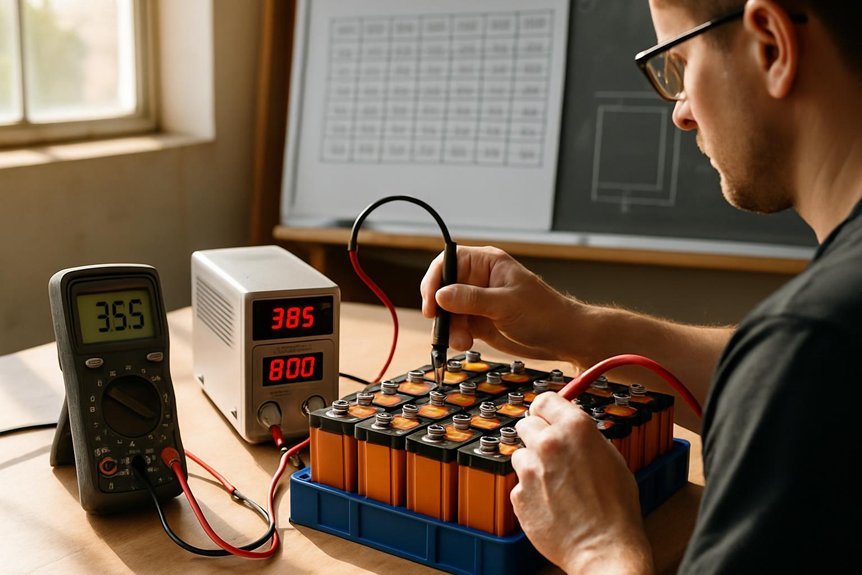
Sizing your LiFePO4 bank for safe charging follows from grasping C-rates: you must align stored capacity with the charging current you apply. We approach sizing by defining target charge C-rate based on bank capacity and operating temperature, then selecting a charger that maintains that rate within tolerance. We compute maximum recommended current as C_rate × total Ah, with a safety margin for aging. We verify that each cell group shares current evenly, minimizing imbalance. We assess charger compatibility to ensure the chosen unit supports the bank’s voltage and chemistry profile, including HV stage behavior. We cross-check BMS limits, ensuring the BMS can terminate or reduce charging before overcurrent or voltage thresholds are reached. This disciplined approach prevents overstress and extends cycle life.
Quick-Start: Pick Your First Charger Amperage for LiFePO4
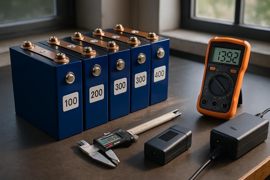
Are you ready to set a practical starter charger amperage for your LiFePO4 bank? We’ll establish a conservative baseline, then adjust with charging fundamentals in mind. Start with a modest amp rating that matches the bank’s capacity, ensuring compatibility with your BMS and charger. Prioritize safety considerations by confirming proper voltage limits and thermal safeguards before connection. In practice, we recommend a first-pass amperage near 0.2C to 0.3C for initial conditioning, then monitor cell voltages and temperatures during the first cycles. Use this table as a quick reference for the baseline setup.
| Parameter | Target value |
|---|---|
| Bank size basis | 0.2C–0.3C starter amp |
| Safety checks | Voltage, temp, BMS signaling |
Matching Amperage to LiFePO4 Chemistry and Temperature
We align charge rates with LiFePO4 chemistry and operating temperature to prevent adverse reactions and optimize longevity. We’ll compare inherent charge-rate limits to ambient and pack temperatures, adjusting amperage as needed to stay within safe thresholds. This discussion centers on temperature-adjusted amps and how they interact with the chemistry’s maximums and recommended charge profiles.
Charge Rate Limits
Determining the correct charge rate for LiFePO4 banks hinges on matching amperage to the chemistry and operating temperature. We define charge rate limits by cell chemistry, pack configuration, and safe voltage thresholds, then verify with controlled tests. Our approach sets maximum continuous currents that neither overshoot a safe SOC window nor provoke undue internal heating. We segment limits into bulk, absorption, and termination phases, ensuring the charger transitions occur within spec. We document derating rules for elevated temperatures and aging, maintaining a conservative margin to preserve cycle life. We evaluate parallel strings for current sharing, balancing impedance and conductor resistance. Applying these limits supports energy efficiency and predictable performance, enabling reliable sizing of chargers, fusing, and protection schemes while avoiding thermal runaway risks.
Temperature-Adjusted Amps
Temperature adjustments directly shape the safe, usable current for LiFePO4 banks. We examine how temperature influences charge current decisions, then translate those effects into practical limits. At higher temperatures, chemistry accommodates higher currents, but this increases stress and potential degradation, demanding tighter oversight for charging safety. At lower temperatures, internal resistance rises and cell polarization increases, reducing effective capacity and necessitating reduced amperage to maintain safety margins. We propose a temperature-adjusted framework: determine baseline charging current from nominal ratings, then apply correction factors based on measured ambient and pack temperature. Implement dynamic monitoring to prevent overcurrent events when temperature spikes occur. This method preserves balance, minimizes heat buildup, and aligns with charging safety, ensuring consistent performance across environmental conditions.
Managing Heat: Charging Limits and Cooling Strategies
How can we prevent overheating while charging LiFePO4 banks, and what concrete steps guarantee safe operation? We outline disciplined limits and active cooling to maintain stable temperatures. Set charger current to within manufacturer-recommended ranges per bank size, then monitor cell temps continuously. Use airflow, heatsinks, and, where needed, resistive or active cooling during high-current cycles. Implement thermal sensors at pack hot spots and trigger auto-reduction of charging current if thresholds are exceeded. Maintain clear separation between charging and discharging temps, and verify that venting paths remain unobstructed. Regularly inspect connections to prevent contact resistance. Heat dissipation strategies and thermal runaway prevention hinge on predictable, responsive control logic, backed by verified temperature data and fail-safe shutdowns.
| Sensor | Action |
|---|---|
| Temperature | Auto-limit current |
| Ventilation | Maintain airflow |
| Alarms | Notify and log events |
Practical Guidelines by Use Case: Solar, Marine, Off-Grid
We’ll outline practical guidelines by use case, focusing on solar charging, marine environments, and off-grid setups. We start with solar charger sizing and marine/off-grid rules, emphasizing methodical selection aligned to LiFePO4 bank capacity and charging limits. Our aim is clear criteria and concise rationale to guide your charger amperage choices.
Solar Charger Sizing
Solar charger sizing hinges on the specific use case and system goals, so we tailor the amperage to match daily energy production, acceptable charger voltage, and charging efficiency. We evaluate solar array current and voltage under typical irradiance, then select a charger that sustains proper LiFePO4 charging profiles without exceeding cell limits. Our method accounts for derating factors, battery temperature, and regulation accuracy, ensuring stable acceptance currents and minimized heat. We consider battery ergonomics to avoid excessive cycling or wake-sleep transitions that erode usable capacity, preserving long-term operability. We also assess warranty implications, ensuring chosen chargers align with manufacturer specifications to maintain coverage. In practice, we document charge curves, efficiency losses, and controller compatibility, delivering a repeatable sizing procedure that supports predictable daily autonomy and system resilience.
Marine Off-Grid Rules
Ever wonder how marine off-grid systems stay reliable under harsh conditions and limited daylight? We approach rules with discipline, documenting constraints, and aligning findings with battery metallurgy and lifecycle tradeoffs. We’ll map practical guidelines to vessel use, weather, and maintenance cycles, ensuring charger amperage choices respect temperature, SOC limits, and array geometry. System reliability hinges on matching charge profiles to LiFePO4 behavior, avoiding overcurrent during peak loads, and preserving long-term capacity. Now, a concise visualization:
| Environment | Demand Pattern | Mitigation Action |
|---|---|---|
| High load seas | Short day, cloudy | Boost current during sun peaks |
| Low sun seasons | Prolonged equalization | Schedule gradual tapering |
| Temperature swings | Cold starts | Insulated charging path |
Table plus notes emphasize battery metallurgy awareness and lifecycle tradeoffs for durable, predictable operation.
Verifying Charger Compatibility With Your BMS
To verify charger compatibility with your BMS, start by confirming the charger’s voltage and current ratings align with the BMS’s input specifications and the LiFePO4 battery bank’s design. We then verify that the charger’s output is stable under load, with voltage tolerance within the BMS’s permissible range. Next, we monitor BMS signals during initial connection and progressive charging, ensuring the BMS acknowledges charge current without entering fault mode. We confirm that the charger safety features — short-circuit, overcurrent, and thermal protections — engage as intended. We document any discrepancies and adjust settings or select an alternative charger accordingly. Finally, we validate charging termination occurs according to the BMS’s voltage thresholds. This methodical check minimizes risk while preserving long-term cell health and charger safety.
Troubleshooting Charging Issues and Signs of Stress
When charging issues arise, we start by confirming that the charger and BMS are still operating within their designed parameters and that the LiFePO4 bank is responding as expected under load. If voltages spike or drift beyond acceptable ranges, we document timestamped readings and isolate the likely subsystem, whether input supply, wiring, or cell balance. We perform a controlled load step and monitor current, temperature, and termination behavior, noting any abnormal heat or lingering high impedance. Signs of stress include degraded capacity, increased internal resistance, or uneven cell voltages, which trigger two word discussion ideas about diagnostic focus. We then apply targeted remedies, avoid reactive repairs, and reassess after each adjustment to validate stability and charging efficiency, preserving safety margins throughout the process. troubleshooting stress.
Frequently Asked Questions
Can Charger Amperage Affect Lifepo4 Cycle Life Beyond C-Rate Limits?
Overcharging risks can arise if charger amperage exceeds LiFePO4 cycling limits, potentially shortening life. We analyze exact C-rates, monitor voltage tails, and maintain conservative amperage to protect Battery cycling limits while ensuring efficient, safe charging.
How Does Temperature Influence Charger Amperage Safety for Lifepo4?
Temperature safety guides us: as ambient rises, charger amperage should drop to preserve LiFePO4 health, preventing overheating. We monitor cell temps, maintain cooling, and optimize charging efficiency while keeping within safe current limits for reliable operation.
Is Higher Amperage Always Faster Charging for Lifepo4 Banks?
Higher amperage isn’t always faster for LiFePO4; charging efficiency drops if we push too hard, so we balance rate with peak heat management and cell balance. We monitor temps, then adjust current to optimize charging efficiency.
Do Battery Aging and Sulfation Alter Optimal Charger Amperage?
We must adjust, yes: aging effects and sulfation implications can shift optimal charger amperage. We approach methodically, measuring capacity loss, internal resistance, and sulfation signs; we calibrate amperage to compensate, like tuning a rhythm for reliability.
Should I Oversize Charger Amperage for Future Bank Expansion?
Yes, we shouldn’t oversize arbitrarily; we oversize cautiously for future expansion, balancing efficiency and safety. We’ll document parasitic loads, peak demand, and wire sizing, ensuring an oversize charger supports planned bank growth without overstressing cells.
Conclusion
We’ve laid out a clear, methodical approach to selecting and monitoring LiFePO4 charging amperage. By starting at 0.2–0.3C, adjusting for temperature, respecting BMS and charger voltage, and enforcing auto-current limiting, we minimize stress and aging. Think of our process as tuning a fiber optic line: small, precise changes yield clean, safe performance. With continuous monitoring and proper cooling, we maintain reliable, safe charging across solar, marine, and off-grid setups.