We examine BMS compatibility by aligning chemistry, voltage, and protection schemes so a pack can be charged, balanced, and discharged safely. We’ll verify protocols, data interfaces, and timing to minimize translation layers and latency, while confirming form factor, wiring, and thermal design fit the enclosure. Our goal is to maintain traceable calibration and fault handling, ensuring compliant, predictable system behavior. There’s more to contemplate before making a choice, and that requires careful, structured evaluation.
Key Takeaways
- Align chemistry, voltage ranges, and protection schemes to ensure safe monitoring and reliable state-of-charge estimation.
- Evaluate interfaces, protocols, and data integrity to guarantee interoperable, low-latency communication and traceable data flows.
- Map fault handling to deterministic actions and safe state transitions across modules and system protection layers.
- Consider physical packaging, form factor, harnesses, and connector standards to ensure proper fit and reliability.
- Ensure documentation covers decisions, testability, and compliance to standards for traceable safety justification.
What BMS Compatibility Means and Why It Matters
Understanding BMS compatibility starts with a simple question: will the BMS manage this specific battery pack safely and effectively? We assess compatibility by aligning the pack’s chemistry, voltage range, and current limits with the BMS architecture. Our focus is on safe operation, accurate state monitoring, and reliable protection features, including overcharge, overdischarge, short-circuit, and temperature controls. We evaluate integration points such as communication protocol, data logging, and fault reporting, ensuring no mismatch creates latency or misreadings. Cost efficiency emerges when protection schemes minimize wear and unnecessary replacements. Regulatory compliance remains essential, as standards govern safety, labeling, and fault handling. In sum, true compatibility balances performance, protection, and governance, guiding designers toward predictable behavior, thermal stability, and durable, compliant systems.
Match Cell Chemistry and Voltage Ranges
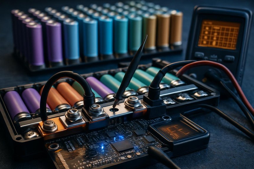
We must choose the right cell chemistry and confirm compatible voltage ranges before integrating cells into a BMS. We consider how chemistries behave differently under charging, balancing, and thermal conditions to prevent misalignment. By matching chemistry and voltage expectations, we set a solid foundation for safe, reliable battery management.
Matching Cell Chemistry
Why does matching cell chemistry and voltage ranges matter in a BMS? We analyze compatibility to ensure safe operation, predictable performance, and accurate state monitoring. By aligning chemistry and voltage windows, we prevent overstress, misleading protections, and inconsistent cell balancing. Our focus remains on safety, efficiency, and longevity, not conjecture.
- We evaluate chemistries for charging safety and thermal behavior, establishing safe voltage ceilings.
- We verify that the BMS supports the actual cell chemistry’s impedance, capacity, and aging profile.
- We align recommended charge/discharge voltages with pack topology for reliable monitoring.
- We confirm thermal management requirements integrate with charging strategies and protection schemes.
Aligning Voltage Ranges
Are voltage ranges truly aligned with cell chemistry, and if not, what risks emerge for a BMS? We analyze how mismatches affect safety, accuracy, and longevity. When cells differ in chemistry, their nominal and full-charge voltages vary, shifting pack upper and lower limits. A BMS must translate these values into reliable state-of-charge estimates, balancing currents without overvoltage or undercharge. Misalignment can trigger premature fault handling, inaccurate cell balancing, or thermal runaway in worst cases. We emphasize consistent voltage windows across cells and modules, verifying specifications during design and commissioning. For ongoing reliability, couple proper pack calibration with periodic bms troubleshooting to detect drift in voltage sensing, temperature effects, and aging. Clear documentation supports calibration updates and reduces misinterpretation of sensor data over the system’s life.
Choose Protocols and Data Interfaces
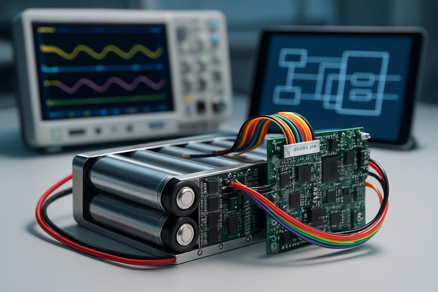
Choosing the right protocols and data interfaces hinges on clarity of data needs, interoperability, and the target system’s performance. We outline how to approach protocol selection and data interface choices with precision and focus.
- We assess data granularity, timing, and error handling to pick compatible protocols.
- We evaluate hardware compatibility, cabling, and electrical characteristics for robust interfaces.
- We prioritize interoperability to minimize translation layers and latency.
- We document data flows, update cycles, and failure modes to ensure traceability and compliance.
Our approach remains analytical: favor standard, widely adopted protocols where possible, verify data integrity, and align interfaces with the BMS’s processing capabilities. This prevents bottlenecks and supports scalable growth. Protocol selection and data interface choices shape reliability, diagnostics, and safety across the system.
Hardware Form Factor and Wiring for Your Pack
We start by aligning our pack’s form factor with the BMS’s mounting and cooling requirements, then evaluate how wiring harnesses fit within the enclosure and routing constraints. We’ll assess connector standards, cable gauges, and spacing to ensure reliable interconnections without stress or interference. This discussion sets the baseline for safe, scalable integration of Pack Form Factor, Wiring Harnesses Fit, and Connector Standards Alignment.
Pack Form Factor
The Pack Form Factor defines how a battery pack is physically arranged and wired, directly shaping thermal management, electrical performance, and integration with the BMS. We approach this topic with precision, mapping constraints to outcomes and avoiding ambiguity. Our focus is on how form factor influences reliability, serviceability, and safety margins for enclosure fit and battery sizing. We outline a disciplined path below:
- Assess footprint, height, and port layouts to ensure enclosure fit aligns with system constraints.
- Compare cell geometry and stack approaches to optimize thermal pathways and current distribution.
- Verify connector placement, harness routing, and accessibility for maintenance.
- Define tolerances and mounting interfaces to support consistent battery sizing and repeatable assembly.
Wiring Harnesses Fit
How can we guarantee wiring harnesses fit without compromising pack integrity or serviceability? We approach this by aligning form factor, routing, and connector standards to minimize interference with cells and cooling paths. Our method emphasizes standardized harness lengths, protected conduits, and modular connectors that tolerate vibration while preserving serviceability. We assess tolerance stacks, strain relief, and EMI considerations to ensure reliable performance across operating ranges. By documenting exact harness profiles, we enable repeatable installation and easier field maintenance. Below is a visual representation of ideas.
| Harness Profile | Routing Considerations | Verification Criteria |
|---|---|---|
| Standardized length | Avoids pinch points | Fit test, clearance check |
| Protected conduit | Supports vibration | Torque and tension limits |
| Modular connectors | Easier replacement | Connector integrity, pull tests |
Connector Standards Alignment
Connector standards alignment shapes how we balance hardware form factor with reliable wiring for the pack. We assess interfaces for current, voltage, and temperature ratings to minimize failure modes and simplify assembly. Our goal is predictable performance across environments without surprises.
- We map connector families to pack dimensions to avoid overhangs, misfits, or stress on pins.
- We evaluate pin count, polarity, and locking mechanisms to reduce fault rates and facilitate maintenance.
- We verify cable gauges, strain relief, and routing to prevent impedance changes and insulation wear.
- We scrutinize compatibility pitfalls and supplier documentation to avoid mismatches and hidden costs, while guarding against vendor lock in.
Informed selection supports long-term reliability, safer maintenance, and clearer interoperability across BMS ecosystems.
Align Safety Features and Fault Handling
Aligning safety features and fault handling across a BMS is essential to ensure predictable responses under fault conditions and to minimize risk to people and cells. We approach this with a formal, evidence-based mindset, detailing how module-level protections cascade to system-wide behavior. We map fault states to clear actions, ensuring deterministic shutoffs, alert signaling, and safe state transitions that halt charging when thresholds are breached. We align fault handling with charging safety, so that protection trips trigger orderly energy management rather than abrupt shutdowns that could damage hardware. Our emphasis is on traceability, testability, and compliance with standards, documenting decision criteria and recovery procedures. This disciplined alignment reduces ambiguity, supports diagnostics, and enhances overall BMS reliability while preserving user safety and pack longevity.
How to Evaluate and Select a Compatible BMS for Your Pack
When selecting a BMS for your pack, we assess compatibility across cell chemistry, voltage range, current ratings, communication interfaces, and form factor to guarantee reliable integration. Our approach is methodical, prioritizing measurable specifications and practical fit.
1) Evaluate cell chemistry and chemistry-specific protections to ensure correct chem compatibility and safe fault responses.
2) Verify voltage range alignment, state-of-care limits, and charge/discharge boundaries to prevent over-stress.
3) Inspect current ratings, peak handling, and continuity protections for reliable operation under load.
4) Confirm communication interfaces, topology, and duty cycle support, plus physical fit in the enclosure (bms packaging) and thermal management considerations for heat dissipation.
We emphasize concise documentation and traceable selections to support compliant integration.
Frequently Asked Questions
How Does BMS Firmware Update Affect Compatibility?
We can say: bms firmware updates can affect compatibility, potentially altering calibration and communication with mixed chemistries, changing compatibility impact, and imposing new pack constraints; we assess how revisions interact with sensors, cell models, and safety interlocks.
Can Mixed Cell Chemistries Exist Within One Pack?
Yes, mixed chemistries cannot safely share a single pack. We’d recommend separate modules; monitor risk of imbalance, protection, and safety trips. In practice, we avoid mixed chemistries within one pack to maintain reliability and compliance.
Do BMSS Support Custom Fault Thresholds?
Yes, BMSs can support custom thresholds and fault tuning. We’ve seen teams reduce fault-trigger rates by up to 40%. We’ll analyze specs with you, guarantee safety margins, and tailor custom thresholds for your pack’s fault tuning needs.
Are Non-Destructive Testing Methods Compatible With BMSS?
Non-destructive testing is not universally compatible with every BMS, but it can be integrated with careful scheduling and data tagging; we assess battery pack compatibility and impact on fault thresholds before proceeding.
How Does Ambient Temperature Influence BMS Compatibility?
Ambient temperature affects BMS compatibility by altering sensor readings and communication timing; we monitor shifts and verify firmware version alignment. We’ll adjust thresholds, confirm robust interop, and ensure consistent performance across environments for reliable operation.
Conclusion
We, as practical partners, preserve precise, predictable performance by prioritizing compatible chemistry, voltage, and communication. We’ll verify voltage ranges, matching cell chemistry, and minimizing translation latency. We’ll scrutinize protocols, data interfaces, and wiring, ensuring seamless signals and sturdy safeguarding. We’ll harmonize safety features and fault handling, holding hardware, harnesses, and enclosure fit to rigorous standards. In short, we’ll confirm coherent coordination, clear calibration, and compliant continuation—creating confident, compact, cohesive compatibility that sustains dependable, safe power.


 Compatibility)