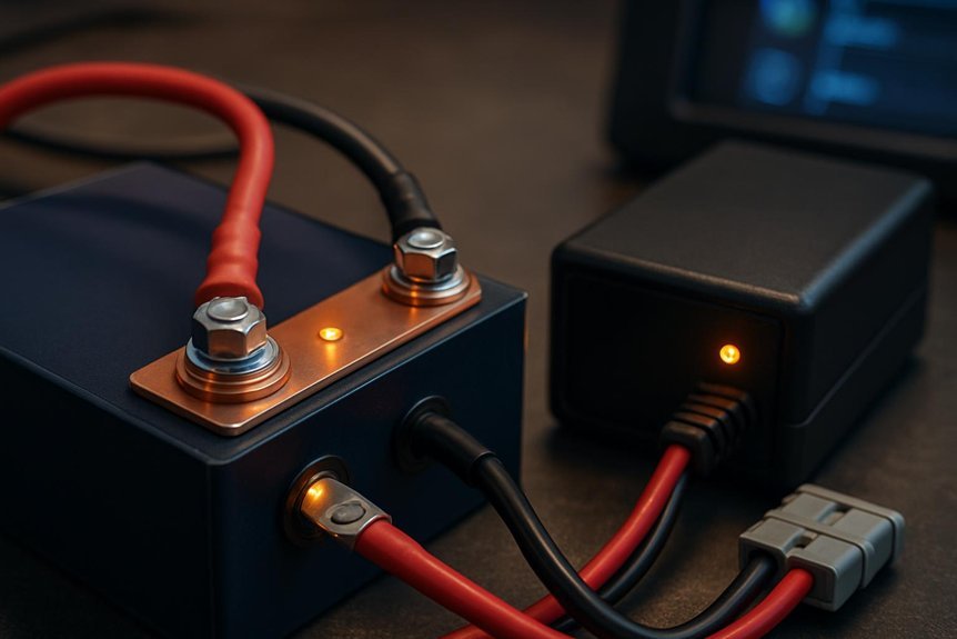
We methodically approach LiFePO4 charger and battery connections by starting with careful live measurements at the charger output, battery terminals, and ground points, then inspect cables, terminals, and connectors for corrosion or wear. We cross-check fault codes, verify charging stages and termination, and re-seat or replace components as needed. We’ll document every finding, confirm compatibility, and map fault patterns to fixes, then determine whether we’ve eliminated obvious failure modes—or if something subtler remains unresolved. The next step sharpens our focus.
Key Takeaways
- Inspect and torque all terminals, cables, and connectors; look for corrosion, looseness, and insulation damage that cause resistance or open circuits.
- Verify charger output versus rated specs under load; check for overshoot, undershoot, or lingering current indicating regulation or misconfiguration.
- Real-time: measure pack voltage and ground references with a multimeter while energized to spot grounding or cross-connection issues.
- Cross-check BMS roles and fault codes; ensure charger charging criteria match battery requirements and proper termination behavior.
- Document symptoms and fault codes precisely, reproduce faults with controlled loads, and correlate with temperature and environmental factors.
Spot Obvious LiFePO4 Charging Faults at a Glance
Spotting obvious LiFePO4 charging faults at a glance means focusing on the clues that don’t lie: charging current, voltage, and termination behavior. We examine patterns, not excuses, and map them to known fault modes. If charging current fades prematurely or remains erratic, we flag potential sensor or controller calibration issues, including drift that masks true state. Voltage readings that overshoot, undershoot, or oscillate indicate regulation faults or cell group imbalance, demanding cross-checks against pack temperature and SOC estimates. Termination behavior—whether current cuts exactly at the intended cutoff or lingers—reveals timing misconfigurations or software locks. We also consider environmental factors like lack of sunlight and unintended system activity, which can mask faults. Memory leaks in control firmware may mimic charging anomalies, warranting a diagnostic review.
Tighten Terminals and Remove Corrosion Safely
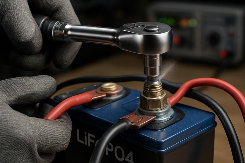
How can we guarantee a solid, long-lasting connection? We begin with clean, dry contacts, then tighten terminals to the correct torque, not to overtighten. We inspect lug interfaces for flat seating and shim any spacing issues that could compromise contact area. We use a calibrated tool to avoid over- or under-torque, rechecking after initial run-up. If corrosion exists, we remove corrosion carefully with a non-metallic brush or approved cleaner, ensuring we don’t create conductive debris. We then re-clean, dry, and reassemble, applying a light, compatible anti-corrosion compound only where specified. We verify continuity with a multimeter and confirm voltage stability under load. Finally, we document torque values and cleaner type for future maintenance, ensuring repeatable, reliable connections.
Inspect Cables and Connectors for Damage
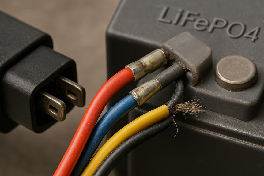
We start by systematically inspecting every cable and connector for signs of wear, damage, or heat impact. We methodically check insulation integrity, insulation degradation signs, and any softened or cracked jackets. We examine connector housings for corrosion, bent pins, and looseness that could cause intermittent contact. We also test for connector overheating indicators, including melted seals or unusual warmth after short runs. To emphasize critical areas, note the table below.
We inspect every cable and connector for wear, damage, and heat impact, documenting insulation and housing issues for targeted repairs.
| Focus | Indicator |
|---|---|
| Impacted wiring | Visible cracking, abrasion, or insulation wear |
| Connectors | Loose fit, bent pins, or discoloration indicating overheating |
Careful documentation follows each finding, so we can plan targeted repairs without overhauling healthy segments. This keeps the system reliable and reduces risk of future failures.
Confirm LiFePO4 Charger Compatibility: Voltage and Current
To confirm LiFePO4 charger compatibility, we must verify that the charger’s voltage and current specifications align with the battery’s requirements. We start by checking the battery’s nominal voltage, float, and charge voltages, ensuring the charger’s output remains within tolerance. Next, we compare current ratings: charger max current should not exceed recommended charging current for the pack, and the charger’s startup surge must be within safe limits. We assess whether the charger supports proper charging stages and termination criteria, avoiding overcurrent conditions. We perform a compatibility assessment by cross-referencing datasheets and real-world measurements, noting any deviations. This discipline promotes charging safety, reduces heat buildup, and preserves capacity. Correct matching avoids premature aging and potential faults during operation.
Understand What the BMS Should Do During Charging
We’ll outline what the BMS should handle during charging to keep packs safe and accurate. We’ll cover the BMS charging role, how the battery pack communicates status, and the practices that ensure safe charging. Our aim is a clear, methodical baseline that guides diagnosis and informs reader decisions.
BMS Charging Role
How should the BMS behave during charging to protect LiFePO4 packs and assure reliable operation? We, as engineers, outline precise BMS charging roles to prevent overcharge, overheating, and imbalance. First, the BMS monitors cell voltages and temperatures in real time and enforces safe limits, terminating or tapering charge as needed. It manages CC/CV charging, preserving optimal end-of-charge voltage while avoiding voltage overshoot. It controls current flow during balancing, prioritizing early detection of weak cells and initiating active or passive balancing as appropriate. It validates charger compatibility, ensuring secure communication and proper safety interlocks are engaged. It logs fault conditions for diagnostics, and it communicates clear status to the system. In short, bms roles center on safety, reliability, and accurate state awareness.
Battery Pack Communication
What communication does the BMS perform during charging to guarantee safe, reliable operation? We examine how the BMS sustains a robust link with the charger and the battery pack. First, it negotiates a compatible communication protocol, ensuring mutual awareness of state, current limits, and voltage targets. Next, it monitors cell voltages, temperatures, and pack current, reporting deviations in real time and triggering protective reactions when thresholds are breached. We verify proper state-of-charge estimation and balance status, confirming that balancing activity aligns with charging progression. The BMS also authenticates charger identity and verifies firmware integrity to prevent spoofing or faults. Finally, it logs events and communicates faults to the user interface for diagnostics, preserving a traceable, auditable charging sequence.
Safe Charging Practices
Are we sure charging remains safe if the BMS doesn’t enforce strict limits and timely responses? We start with a clear expectation: the BMS must monitor voltage, current, and temperature, and it must intervene before conditions become unsafe. Our focus is on safe charging practices, not guessing at risk. The BMS should prevent irreversible damage by stopping charging if cell voltages drift, temperatures rise beyond thresholds, or pack impedance indicates imbalance. It should enforce gradual current tapering near full charge and verify proper balance between cells. Misuse prevention hinges on accurate state estimation, fault logging, and fail-safe alarms. We assess connector integrity, cable heat, and charger compatibility, ensuring the system responds to anomalies promptly. Correct configuration, routine checks, and documented procedures close the loop on safe charging.
Live Multimeter Testing: Step-by-Step Measurements
We approach Live Multimeter Testing by laying out the three core steps: Set Up Multimeter, Measure Charger Output, and Verify Battery Connection. We’ll outline precise test points, guarantee correct ranges, and document observed values to verify proper charging behavior. If results differ from expected, we’ll isolate the fault with targeted measurements and clear, actionable conclusions.
Set Up Multimeter
Setting up a multimeter for live testing is a precise, methodical process that we’ll follow step by step to avoid misreads or damage. We approach each measurement with charging basics and safety protocols in mind, ensuring probes connect correctly and the device rests on a stable surface before touching any terminals.
| Step | Action |
|---|---|
| 1 | Inspect meter and probes for damage; set to volts or current as required. |
| 2 | Power down equipment when possible; connect test leads to the appropriate ports. |
| 3 | Calibrate or zero if needed; verify ranges match expected values. |
| 4 | Recheck connections; power on and perform non-contact checks before touching terminals. |
Measure Charger Output
Now that the multimeter setup is ready, we’ll measure the charger output with live testing. We begin by confirming the charger is unplugged, then connect the meter’s ground probe to the system ground and the positive probe to the charger output lead. We plug in, select DC volts, and observe the reading at nominal load. We compare the measured voltage to the charger’s rated output, noting any deviation beyond tolerance. If readings drift or show instability, we document whether symptoms are sudden or gradual. We also watch for inconsistencies that could produce unclear symptoms, such as transient spikes or oscillations. Check for improper grounding by verifying a solid, low-impedance path to earth; any resistance here can mask true output behavior and mislead diagnosis.
Verify Battery Connection
Can the battery connection be validated in real time with the multimeter while the system remains energized? We’ll verify by measuring pack voltage at the terminals first, then check cross-connection between battery leads and charger leads. Grounding and chassis references are confirmed next to ensure a stable baseline. We document expected voltages for LiFePO4 cells and compare them with live readings, noting any drift under load. We avoid non technical misconceptions by distinguishing voltage drop from resistance, and we use a low-resistance range to detect loose contacts. If readings diverge, we re-seat connectors, clean corrosion, and repeat tests to rule out novice mistakes. Finally, we record results, assign corrective actions, and ensure ongoing monitoring while maintaining safety protocols.
Identify Voltage Drops and Grounding Issues
Where do voltage drops and grounding issues typically hide in a LiFePO4 charging system, and why do they matter? We approach this analytically, identifying symptoms, causes, and remedies without ambiguity. Voltage drops undermine charge efficiency and can mimic faulty components, while grounding issues threaten safety and measurement integrity. Together, they distort voltage readings and undermine protection logic.
Where voltage drops and grounding issues hide, threatening accuracy and safety in LiFePO4 charging systems.
- Inspect connector integrity and wire gauges for resistive losses.
- Verify battery pack grounding and chassis ground continuity.
- Measure voltage differentials at inlet, within the BMS, and across sense lines.
- Isolate segments to pinpoint hidden resistances or loose returns.
Address each finding with targeted tightening, re‑term, or component replacement, then re‑test. This disciplined checks a LiFePO4 system’s reliability and protects both equipment and personnel.
Read Charger Indicators and Fault Codes Accurately
We systematically read fault codes and charger indicators to establish a clear fault taxonomy. By matching codes to documented definitions and cross-checking with indicator patterns, we identify the specific failure mode. We then assess consistency across readings to avoid misinterpretation and guide precise corrective steps.
Read Fault Codes Accurately
Accurate fault code reading is essential to diagnose LiFePO4 charger and battery issues quickly and reliably. We adopt a precise, repeatable approach to fault diagnostics, focusing on reproducibility and traceability. Our method minimizes ambiguity and aligns with safe charging etiquette.
- Record exact fault codes verbatim, including any subcodes.
- Note the time, battery state, and charger model to contextualize codes.
- Cross-check codes against the manufacturer’s tables and firmware notes.
- Test with controlled load and measure responses to confirm the fault.
Following these steps ensures accurate interpretation, reduces misdiagnosis, and preserves safety. We maintain disciplined documentation, confirm patterns across cycles, and avoid assumptions. This disciplined routine promotes reliable troubleshooting, enhances charging etiquette, and supports quick restoration of normal operation when issues are resolved.
Interpret Charger Indicators Properly
How can we read charger indicators reliably to pinpoint faults? We approach indicators methodically, not by guesswork. First, we identify the charger’s active signals, matching each LED pattern or screen message to the documented fault taxonomy. Next, we correlate indicators with symptoms in the battery path—voltage, current spikes, or temperature readouts. We document the sequence of events, noting whether warnings precede a shutdown or appear during charging. We compare indicators against known fault codes, ruling out transient fluctuations caused by connection wiggle or low-quality adapters. We verify consistency across cycles to confirm a persistent fault. Informed by these steps, we inform users clearly and avoid jargon, delivering precise interpretations that support swift diagnostics and informed decisions.
Common Fault Patterns and Proven Fixes
Common fault patterns in LiFePO4 charger and battery connections typically follow predictable sequences: loose terminals, corroded contacts, and mismatched or damaged connectors. We document these patterns as diagnostic hooks we can rely on to assess battery health and charging quirks without guesswork.
- Inspect terminals for looseness and verify torque specs, noting any movement during connection.
- Test contact surfaces for corrosion and resistance; replace or clean as needed to restore conductivity.
- Compare connector compatibility and cable gauge to prevent mismatches that degrade performance.
- Observe charger behavior under load, correlating abnormal faults with potential wiring or contact issues.
These steps tighten our analysis, reduce ambiguity, and guide repeatable fixes for reliable charging outcomes.
Safety, Parts Replacement Thresholds, and Precautions
Should we proceed with a cautious, data-driven approach to safety and replacements? We approach safety with defined thresholds, documenting observed failures and their causes. We establish replacement triggers based on quantitative criteria: insulation wear, connector corrosion, voltage drift, and persistent fault indicators after corrective actions. When assessing safety hazards, we differentiate routine maintenance from high-risk scenarios, prioritizing immediate action for any thermal, smoke, or electrolyte signs. Troubleshooting unrelated issues that could mask true faults gets its own checklist, ensuring no cross‑contamination of data. We balance proactive part replacement against cost and availability, avoiding premature discards while preventing cascading failures. Clear protocol, traceable logs, and worker training guide decisions, ensuring disciplined, repeatable responses to faults.
Frequently Asked Questions
How to Tell if BMS Is Delaying Charging Due to Temp?
We tell you: yes, a temperature warning can delay charging; check BMS logs and charger delay indicators, verify temp sensors, and confirm active protection temp thresholds before proceeding. We’ll methodically rule out sensor errors and wiring faults.
What Charger Voltage Causes Undercharging at Full Pack?
A hypothetical case shows undercharging causes when the charger voltage is too low for a full LiFePO4 pack; we’ve seen it occur with 3.4–3.5V per cell. Charger voltage must meet cell balance requirements to prevent undercharging.
Can a Damaged Balance Lead Mimic a Faulty Charger?
If a damaged balance lead exists, it can mimic a charger fault; a faulty charger combo with a damaged balance can cause erroneous readings. We methodically test connections, inspect the balance lead, and confirm with calibrated measurements before concluding.
How to Distinguish Ground Loops From Actual Battery Fault?
Cross that bridge when we see ground loops vs. battery fault; we’ll methodically check charger voltage, undercharging trends, and charging delay, monitor temperature, inspect balance lead, consider safety, and weigh full pack replacement if needed.
When Is It Safer to Replace the Entire Battery Pack?
We should replace the entire battery pack when faults persist beyond repairing faulty connectors or improper insulation, after thorough testing and failed troubleshooting. We’ll document steps, ensure safety, and verify no hidden damage before replacement.
Conclusion
We’ve walked through a precise, methodical approach to diagnosing LiFePO4 charging issues, from live voltage checks to grounding, and from terminal integrity to BMS behavior. By documenting measurements, tightening connections, and validating charger compatibility, we build a reproducible, safer diagnostic trail. Think of it like tuning a fine instrument: small, deliberate adjustments yield stable, reliable performance. When faults persist, recheck steps, reseat components, and replace only what’s proven faulty.

