We’ll start by aligning the LiFePO4 pack voltage with the charger’s output, using 3.2 V nominal and 3.6 V max per cell to avoid over- or under-charging. Next, we determine system voltage, cell count, and a target C-rate, then factor in parasitic loads, thermal limits, and BMS protections. This requires careful current calculations, safety margins, and verification of wiring, connectors, and efficiency. We’ll outline the step-by-step workflow and common pitfalls, but there’s one critical detail that will shape every choice we make.
Key Takeaways
- Match pack voltage to charger output: choose charger voltage (12V/24V/48V) to align with LiFePO4 nominal 3.2V and max 3.6V per cell for proper regulation.
- Set safe charge currents per configuration: use per-cell 0.5–1C with conservative pack totals, accounting for thermal, BMS, and wiring limits.
- Include parasitics and loads in sizing: factor BMS, sensors, and auxiliaries to determine bulk charging duration and final voltage accuracy.
- Plan protection and fault tolerance: implement overvoltage, overcurrent, thermal protections with clear termination criteria and diagnostics.
- Document workflow and labeling: define assumptions, margins, C-rate, temp targets, and provide clear voltage/current/thermal safety labels for each system.
Match LiFePO4 Pack Voltage to Your Charger
To size a charger correctly, we must first match the LiFePO4 pack voltage to the charger’s output voltage. We align nominal pack voltage with charger regulation to prevent overcharging or undercharging. In practice, 12V, 24V, and 48V systems demand corresponding charger outputs that reflect LiFePO4’s 3.2V nominal per cell and 3.6V maximum per cell. Our reasoning centers on maintaining proper cell balance and leveraging the chemistry’s flat voltage region. We also factor temperature and charging stages, since battery chemistry governs acceptance current vs. voltage limits. Clear safety labeling accompanies every charger configuration, detailing voltage, current, and thermal constraints. By preserving voltage congruence, we minimize stress, ensure predictable behavior, and support safe, reliable system operation.
Set Safe Charge Current per Cell and for the Whole Pack
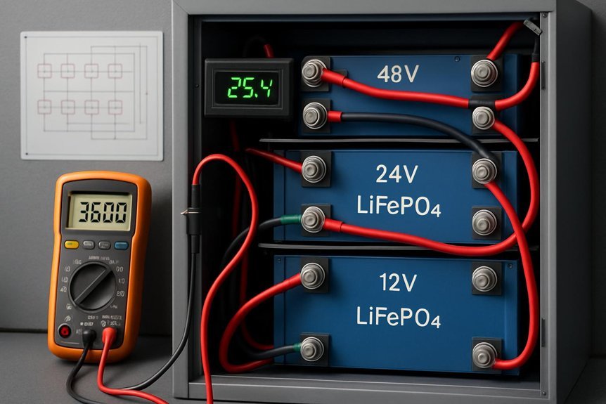
How much current should we allow per cell and for the entire LiFePO4 pack? We answer with precise limits that protect longevity and safety. Per-cell currents typically range from 0.5C to 1C, depending on cell chemistry, temperature, and manufacturer guidelines. For a pack, sum the per-cell current and apply a conservative headroom margin, commonly 0.9C to 1C for 3.2–3.6V cells in series. This preserves capacity and reduces heat, while balancing efficiency tradeoffs. We also account for enclosure, wiring, and BMS limits to avoid bottlenecks. Keep in mind safety misconceptions may lead to overestimation; tighter control improves reliability.
| Per Cell | Whole Pack |
|---|---|
| 0.5–1C | 0.9–1C |
Apply C-Rate: 12V, 24V, and 48V Systems
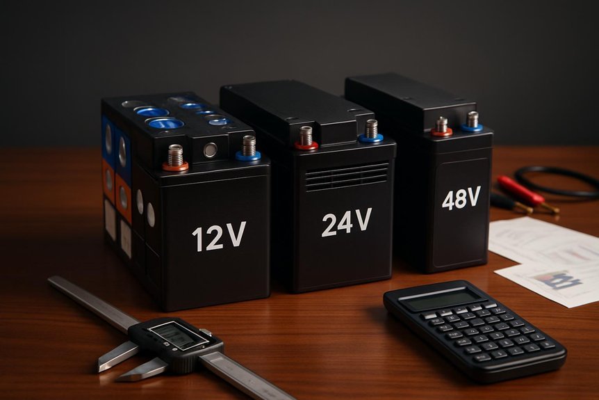
We start by outlining C-rate basics for LiFePO4 and how system voltage defines the practical C-rate window. We then translate those fundamentals into sizing guidelines for 12V, 24V, and 48V configurations, emphasizing how pack voltage interacts with per-cell limits. Finally, we establish concrete, repeatable steps to select C-rate values that meet safe charging objectives while preserving cycle life.
C-Rate Basics For LiFePO4
C-rate is the cornerstone metric for LiFePO4 charging, linking current to capacity and charging time across 12V, 24V, and 48V systems. We’ll define C-rate as a multiple of a battery’s rated capacity (Ah), clarifying how charging current scales with system voltage and cell chemistry. In LiFePO4, C-rate directly affects heat, efficiency, and state of charge transitions, so selecting appropriate multiples matters for longevity. We correct common li ion misconceptions, emphasizing that higher C-rates aren’t universally faster or safer; real-world limits depend on cell quality, thermal management, and charger control. Our focus remains on precise relationships: C-rate, capacity, and time, without conflating voltage classes. This lens guides charger sizing and avoids overreliance on intuition.
System Voltage And C-Rate
System voltage sets the framework for applying C-rate in LiFePO4 charging, because the same C-rate (as a multiple of capacity) translates into different currents on 12V, 24V, and 48V systems. We therefore map C-rate to usable current per configuration, not in isolation. In 12V packs, a given C-rate yields higher current relative to capacity than in 48V systems, altering heat, conversion losses, and thermal management needs. Voltage harmonics become a relevant diagnostic, since higher source impedance and galvanic interactions can modulate effective charging currents during each phase. For recharge endurance, we emphasize consistency of current targets across the system, ensuring the charger maintains the intended C-rate with minimal deviation under typical load and thermal conditions. This alignment supports predictable performance and battery longevity.
Practical Sizing Guidelines
– Ensure
Sizing practical chargers requires mapping target C-rates to concrete current and thermal constraints for each voltage configuration. We, as engineers, translate C-rates into safe charge currents, monitor thermal rise, and respect LiFePO4 limits. For 12V, 24V, and 48V, we align charging profiles with cell balancing, pack impedance, and maximum charger current, avoiding batch mislabeling pitfalls. Our approach minimizes overheating, prolongs cycle life, and preserves pack integrity.
- Consider the system’s peak current capability and ambient temperature limits
- Verify that labeling isn’t misleading marketing and matches actual performance
- Validate thermal throttling margins across each voltage configuration
These checks guard against improper labeling and ensure chargers deliver consistent, predictable performance under real-world conditions.
Account for Parasitic Loads When Sizing
We do not size a charger without accounting for parasitic loads? Not in our precise method. Parasitic load consumes energy when the system appears idle, yet it affects charger sizing meaningfully. We quantify it as the steady-state draw from BMS, instrumentation, and sensing circuits, plus any auxiliary loads that persist during bulk charging or float. Ignoring these drifts yields an optimistic charger sizing error, risking undercharge or frequent cycling. Our approach integrates parasitic load into the required charging current and duration, ensuring the charger delivers the needed final voltage while meeting runtime constraints. We document uncertainty margins and validate with a conservative worst-case assumption. In summary, accurate charger sizing demands explicit parasitic load accounting to avoid overstated performance.
Temperature Effects on LiFePO4 Charging and Mitigation
Temperature can shift LiFePO4 charging performance in tangible ways, so we must account for it alongside parasitic loads. We analyze how temperature affects charging curves, loss mechanisms, and overall efficiency. Our focus: how to implement practical temperature management that preserves charge efficiency across pack voltages and C-rates without overcomplicating the charger design.
- Temperature management strategies that minimize heat rise and prevent derating
- How ambient and pack temps influence Coulombic efficiency and energy losses
- Concrete targeting of safe operating ranges aligned with LiFePO4 chemistry
We quantify impacts on charge efficiency, identify when to throttle, and outline monitoring approaches. By grounding recommendations in thermodynamics and cell behavior, we keep recommendations actionable and robust for sizing decisions.
Essential Charger Features: Balance, Termination, Protections
We assess balance strategies and protection mechanisms as integral charger features. We’ll outline how proper cell balancing, termination logic, and fault protections influence charging accuracy and system safety. This framing sets the foundation for rigorous comparison across 12V, 24V, and 48V LiFePO4 configurations.
Balance Strategies
Balance strategies are critical to safe, reliable LiFePO4 operation, ensuring cells stay within safe voltage windows and the pack remains balanced during charging. We approach balancing as a control objective: minimize disparities, preserve charging efficiency, and maximize pack longevity. Our selection hinges on chemistry, pack size, and charging method, not guesswork. We distinguish passive from active approaches and quantify trade-offs in heat, complexity, and maintenance.
- Impedance-based cell balancing thresholds
- Scheduling of equalization cycles to avoid overbalance
- Monitoring metrics for real-time imbalance detection
We insist on rigorous verification: verify that cell balancing preserves overall efficiency, prevents overvoltage, and sustains capacity equality across a full charge cycle. This disciplined stance guards safety and performance without overengineering the charger.
Protection Mechanisms
What safeguards truly matter in LiFePO4 charging, and how do we implement them without compromising performance? We approach protection mechanisms as a layered control system, not a single feature. First, we embed robust charger safety that detects overvoltage, overcurrent, short circuits, and thermal excursions, then execute timely shutdowns or mitigations to prevent cell damage. Second, we enforce proper termination criteria to avoid undercharging or overcharging, preserving balance and longevity. Third, we implement protections that disrupt fault paths while preserving essential operation, including fault-tolerant filters and watchdog checks. Additionally, load management is integral: the charger adjusts for parasitic draws, transient loads, and supply limits without destabilizing regulation. Precision diagnostics provide clear fault codes, enabling fast recovery and minimal downtime.
Step-by-Step Charger Sizing Calculator Workflow
So, how do we methodically size a charger for 12V, 24V, and 48V LiFePO4 systems? We approach with a stepwise calculator workflow that translates system specifics into charger specs. We verify input ranges, select charging profiles, and apply safety margins, then validate outputs against real-world constraints. We focus on two word discussion ideas: voltage harmonics, stray capacitance, ensuring these factors are reflected in the model. We document assumptions, compute current limits, and check thermal and efficiency envelopes before finalizing charger rating.
Methodically size LiFePO4 chargers via a stepwise, auditable workflow accounting for voltage, current, thermal, and efficiency limits.
- Define system voltage, cell count, and desired charge rate
- Input thermal, efficiency, and protection constraints, then review results
- Cross-check with voltage harmonics and stray capacitance implications
This disciplined flow yields a defensible, auditable charger sizing outcome.
Common Pitfalls and Quick Checks Before You Buy
As we finish sizing a charger with a rigorous, step-by-step workflow, we shift now to practical checks that protect you from common missteps before you buy. We’ll cut noise, confirm specs, and prevent overpromise. Key pitfalls: mismatched voltage class, insufficient current rating, and overlooked heat rise. Quick checks: verify C-rate compatibility, confirm termination options, and assess warranty terms. This discipline keeps you honest about performance and longevity. Below is a concise guardrail table to center your evaluation.
| Criterion | What to verify | Why it matters |
|---|---|---|
| Voltage class | 12/24/48V nominal | Prevents under/over-voltage stress |
| Current rating | Peak vs. nominal | Avoids thermal runaway |
| Thermal spec | ambient and case temp | Ensures safe operation |
| Connector fit | cable size, polarity | Prevents arcing or damage |
| Warranty | duration, coverage | Secures long-term support |
Real-World Setup Scenarios: 12V, 24V, and 48V Case Studies
Are common-size assumptions misleading when charging LiFePO4 packs at different voltages, and how do real-world setups reveal the limits of nominal specs? We examine concrete configurations to quantify how voltage, current, and temperature interact with charger design. Our aim is to map practical constraints to nominal values, revealing where specs diverge from performance. We compare 12V, 24V, and 48V installations, focusing on charger compatibility and system budgeting. We avoid worst-case hype and emphasize repeatable behavior, documenting measurements and tradeoffs. Real-world cases show that wiring, cable resistance, and BMS thresholds shape charge rates more than labels imply, guiding safer, more efficient choices. Clarity in setup, parameters, and monitoring reduces risk and improves overall system budgeting.
- Charger compatibility realities
- System budgeting implications
- Real-world constraint highlights
Frequently Asked Questions
How to Choose Charger Connector Types for Lifepo4 Packs?
We’ll choose connector types that ensure connector compatibility and prevent mismatches, prioritizing standardized, weather-sealed options; verify polarity, gauge, and torque. We’ll follow charging etiquette, using matching connectors, labeled cables, and proper crimping to avoid hazards.
Do You Need a Separate Charger for Multiple Parallel Strings?
We need separate chargers for parallel strings to balance charging, prevent cross-string current, and protect each string’s voltage profile. Using separate chargers keeps control precise, reduces interaction risk, and ensures safe, predictable charging across configurations.
Can Solar Input Affect Charger Sizing and Requirements?
We can say yes, solar input affects sizing. We assess solar compatibility, then match input regulation to charger limits, ensuring tolerances align with charge algorithms; we, as designers, parallel the sources, then verify efficiency, protection, and AMCs.
How to Estimate Charger Heat Dissipation in Compact Installs?
We estimate heat dissipation by multiplying charger efficiency losses by input power, then adjust for ambient temp and enclosure. In compact installs, compute worst‑case dissipation, ensure proper cooling, and verify venting meets safety margins.
Is Wireless/Bluetooth Monitoring Relevant for Charger Sizing?
We’ve tested whether wireless monitoring truly impacts sizing; it doesn’t change core requirements. Wireless monitoring, Bluetooth monitoring may aid diagnostics, but they don’t alter charger capacity, voltage, or heat limits—so our sizing remains data-driven and conservative.
Conclusion
We’ve walked through sizing chargers for 12V, 24V, and 48V LiFePO4 systems with a rigorous, methodical approach. By matching pack voltage to charger output, setting safe charge currents, applying realistic C-rates, and factoring parasitics, temperatures, and BMS protections, you gain a dependable, safe charging plan. We’ve highlighted essential features, workflow steps, and quick checks. In practice, you’ll avoid surprises and stay on track—like crossing a bridge before the river rises, a clear path ahead.